ADVANCED WASTEWATER

Students: Draw flow diagram for the following process:
CAS with/without sand filter
SBR with/without tertiary treatment
Comparison between conventional and SBR process.

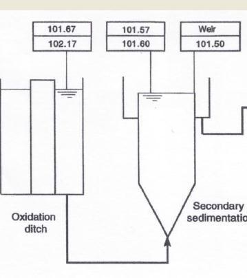
Students: Comment on the hydraulic profile
Hydraulic Profile Example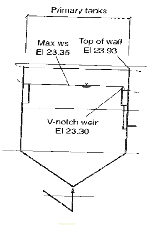
![]() To Chlorination
To Chlorination ![]() To aeration tank
To aeration tank
Source, Metcalf and Eddy,1991
Source, Metcalf and Eddy,2013
Given: head loss (hL) between unit operation/process, tank loss, equipment loss, inlet/outlet loss, minor losses; pipe /valves, channel losses, etc.
Find:
WS elevation?
Weir elevation ? Top of wall ?
Students: Complete work calculation to the next unit process
5


