ADVANCED WASTEWATERWho able to complete answers according to all requirements and in a timely manner.


Students: Draw flow diagram for the following process:
CAS with/without sand filter
SBR with/without tertiary treatment
Comparison between conventional and SBR process.

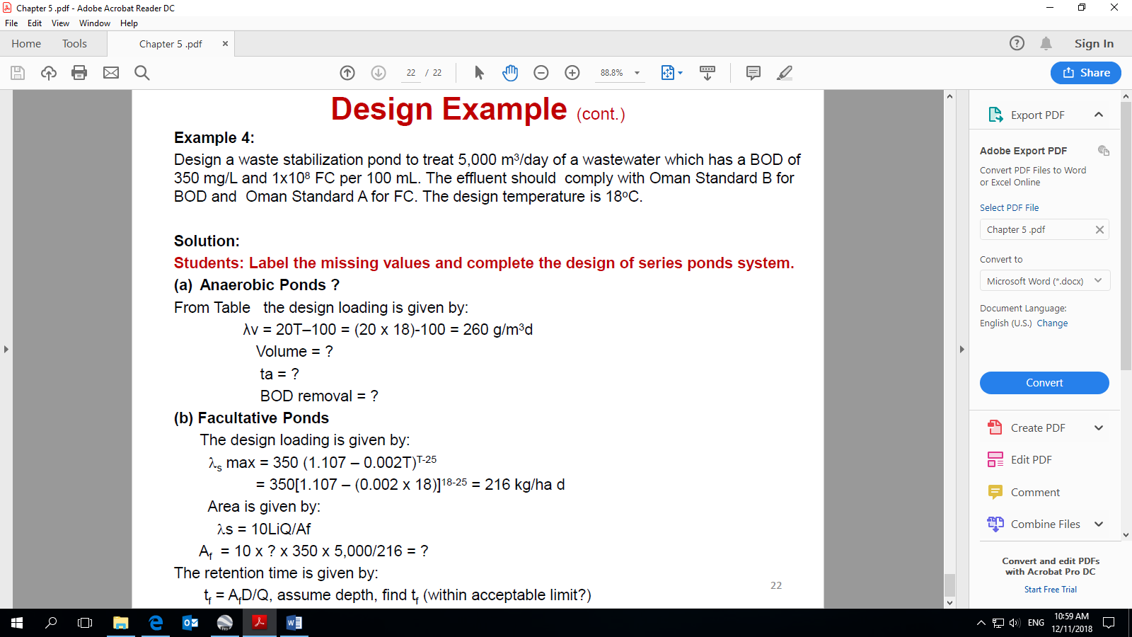
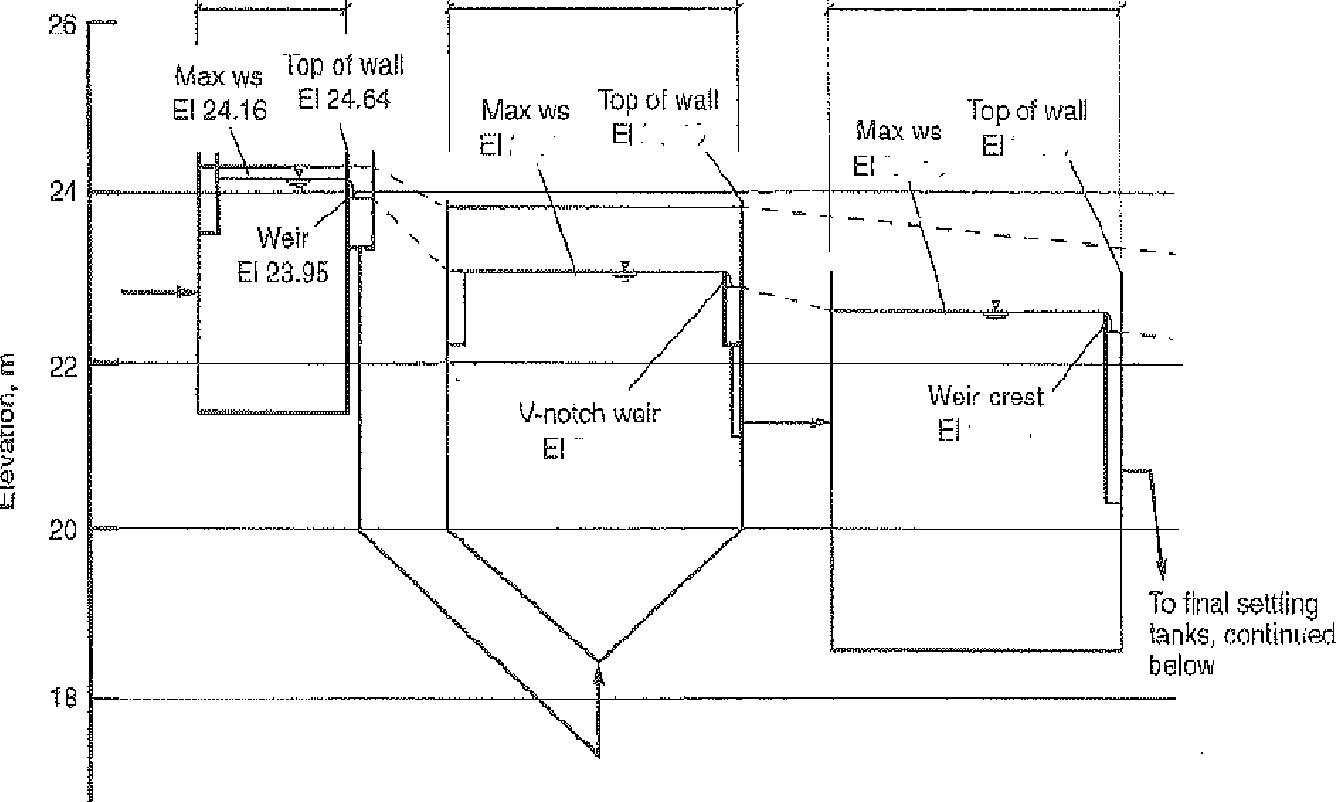
Students: Comment on the hydraulic profile
Hydraulic Profile Example

![]() To Chlorination
To Chlorination ![]() To aeration tank
To aeration tank
Source, Metcalf and Eddy,1991
Source, Metcalf and Eddy,2013
Given: head loss (hL) between unit operation/process, tank loss, equipment loss, inlet/outlet loss, minor losses; pipe /valves, channel losses, etc.
Find:
WS elevation?
Weir elevation ? Top of wall ?
Students: Complete work calculation to the next unit process


Calcu\ate the BOD loading and hydraulic goading of a single-stage trickling filter based on the following data:
- Design assumptions:
![]() Influent flow -1530 m 3/d
Influent flow -1530 m 3/d
![]() Recirculation ratio = 0.5
Recirculation ratio = 0.5
![]() Primary effluent BOD 130 mg/L
Primary effluent BOD 130 mg/L
![]() Diameter of filter 18 m
Diameter of filter 18 m
![]() Depth of media 21 m
Depth of media 21 m
Design a facultative lagoon for a small comminute in Oman when the flow rate is 950 m 3/d and the BOD5 is 315mg/L Use these steps:
Select a reasonable depth and areal loading rate in Oman. Calculate the surface area based on the BOD5 areal load.
Calculate the volume and hydraulic detention time
(jii) If degradation in a facultative lagoon can be modeled as a firstorder process with a degradation rate of 0.2 day-I what will be the effluent concentration from lagoon?
Is the effluent quality complies with Oman Standard B, if not; suggest a measure (by calculation) that could be implemented to allow the pond to achieve better treatment.
A complete mix activated sludge system is designed to serve 60000 people and produce a final effluent that is nitrified and has 5-day BOD not exceeding 25 mg/L. The following design data is available.
Sewage flow = 150 L/person-day
BOD5 = 54 g/person-day
BODu = 1.47 BOD5
Winter temperature in aeration tank = 18 0 C
Yield coefficient Y = 0.6 ; Decay constant Kd = 0.07 per day ; suspended solids (SS) in effluent = 20 mg/L
Substrate concentration in effluent =12 mg/L
Assume any suitable values within acceptable limit,
Calculate:
![]() Aeration tank voluma detention time, F/M. Let the aeration tank be in the form of four square shaped companments opeczted in two parallel rows, what wita be the dimension for each cea.
Aeration tank voluma detention time, F/M. Let the aeration tank be in the form of four square shaped companments opeczted in two parallel rows, what wita be the dimension for each cea.
|
| Return skudge pumping | |
| iii. | Surpgus sludge production |
iv Total oxygen required (carbonaceous and nitrification demand)
(a) Aerators in the activated sludge have oxygenation capacity at field conditions of 65% of the capacity at standard conditions. The mechanical aerators are capable of giving 2 kg oxygen per kWh at standard conditions. If the oxygen requirements for carbonaceous demand and nitrification are 65 kg/h and 77 kg/h respectively, calcuiate the power requirement per year for each person if the population is 60,000![]()
(b) Calculate the organic and hydraulic Eoading for a single-stage trickling based on the following design parameters. Find if the effluent quality for the tracking filter is complied with Oman's Standard A.
![]() Influent flow =1530 m 3/d
Influent flow =1530 m 3/d
![]() Recirculation ratio = 0.5
Recirculation ratio = 0.5
![]() Primary effluent BOD = 130 mg/L
Primary effluent BOD = 130 mg/L
Diameter of filter = 18 m ![]() Depth of media = 2.1 m
Depth of media = 2.1 m
Design facultative pond (without anaerobic pond) to treat 10,000 m 3/day of a wastewater which has a BOD of 100 mg/l. The design temperature is 250C.The minimum retention time for 250C is 5 days.
Design loading for 250C is 350 kg BOD/ha day
Develop the hydraulic profile for maximum flow conditions for the schematic of the part of
 treatment plant (primary tank, aeration tenkj weirs, and top walls) shown below. The total headloss (hL) inc\udes the interconnecting conduits, channels, tanks, etc.
Aerated grit chamber; Given.
Primary tank: hi_ at Max. ws = 0.81 m.
Aeration tank: hLet Max. ws = 0 76 ![]() grit charrnber ?rimaytanks Aeration tanks
grit charrnber ?rimaytanks Aeration tanks
11


