Deliverable Length: 3 pages Provide the following in your assignment:Precondition (identifies the condition that must be met before the sequence proceeds) Identify 3 sequences with at least two
SOFTWARE DESIGN 0
SOFTWARE DESIGN
Charles Williams
CS457 Unit 3 IP
Juan Echeverria
6/3/2019
Table of ContentsTitle Page 1
Table of Contents 2
Introduction 3
System Operation 4
Project Client 5
Software Design Specification 6
Case Diagram……………………………..……………………………………………………………………………………………………………7
Precondition…………………………………………………………………………………………………………………………………….……12
Three Sequence…………………………………………………………………………………………………………………………………….13
Incoming Message to the Sequence………………………………………………………………………………………………………14
Postcondition………………………………..………………………………………………………………………………………………………15
References…………………………………………………………………………………………………………………………………………….16
Introduction
The user interface is a very important aspect of any software. The user needs an interface that he/she can interact with much ease. As a result of this, the designer's major role should be the creation of a most pleasurable user interface that will allow the user to interact with the software without realizing the complications therein in the invoice. This proposal details the outline of the design implementation in relation to user interface designing.
Purpose of the system
The major purpose of designing user interface is to allow easy access, understanding and use of the major purpose of creating user interface are to create elements which anticipate what the user needs and allow the user to gain access, understanding, and application of the elements within the software. The elements within the interface allow interaction both visual and audio between the user and the system software (Chikurtev, Yovchev & Chikurtev, 2016). This software design is aimed to work with the sales software. A sales system allows the interaction of the customer with the system. Through the interface, the user can analyze sales, sales trends and other functions of the system with use as the interface is designed with elements and keys which allow zooming, inversion, and transformation of the images on the system using the user interface.
History of system development
The user interface came into the picture in the year 1981. It was discovered that graphics on the digital user’s interface in conjunction with the pointing device would allow great use of the system. This led to the creation of Xerox Star an integration of desktop computer in the year 1973 (Laaksoet al. 2016). 1.0 Macintosh operating system was the second to be designed with a complete graphical user's interface. The system had only a few of the current operating system which was window-based icons. The window allowed movement using the mouse (Pathak, et al. 2018). In early 2000, there was more advancement with Apple creating Optical devices which developed to magic mouse allowing the user to have more interaction using different fingers (Jones, Clothier, & Jiang, 2018).
System operation
The creation of user interfaces since their creation had not been applied until early 2000. Apple picked up the pace through the creation of an optical mouse. The development and advancement of the mouse led to application and wide application of user interfaces. In the year 2001, UI was introduced with the touch-based user interface. Later, the mouse was designed to become extra-sensitive allowing the designers to scrub buttons from the computer. The use of user interfaces evolved leading to the creation of smartphones in addition to tablets (OGGIONNI, 2018). The UI has enabled users to access and interact with any and all digital substances.
Maintenance
Maintenance is the last step in the designing system. This process entails ensuring that the system can function as purposefully as possible. It’s through this step that user interfaces were developed from the first design to the current design. The process entails feedback from the users is incorporated into the improvements during the last stage of software development. In addition, requests for new features as well as their implementations are analyzed and updated into the user interface. The changes should be backed up (Laudon & Laudon, 2016).
Project client
The client of the project is an online shopping firm. Through the interface, the customers of the firm should be able to view the prices, offers available, warranties of each product, several sales of the product and for how long the product has been on the platform. In addition, the platform through the user interface will allow the customers to order, pay and return products using the application.
Software Design Specification
An online shopping firm is a Company that markets and sell its products on an online platform. By the term online platform, it is the web application that simulates all activities parting the merchandise. The main function of the platform includes order processing, integrated payment for good and service, and communication. However, the current system of the firm has functional issues as discussed below.
Poorly Design and Implemented User Interfaces
The form of control elements of the user interface (input fields, buttons, check boxes, and radio groups) does not look appealing to the users. Form input fields don't clear the data even after the user has submitted the data. This leads to possible replication of the requested data in the event the users mistakenly click the button for the second time. Moreover, the input fields do not perform the minimum client-side validation of input data. These issues lead to erroneous transaction due to the possibility of compromised data in the system's database. Radio groups, buttons, and checkboxes are not orderly positioned.
Low performance
The current system does not execute the user's request at a desirable speed. The system hung when there are many users requesting different services at a given time-it does not scale with the number of transactions per unit time. There is no proper synchronization of executable threads due to poor programming practices.
Various Elements to be Considered When defining System's Objectives
The objectives of the desired system are to have an interactive user interface, to provide high security to business data, to offers services within minimal time, and to reduce operational costs on services. During the determination of these objectives, the following are the fundamental elements that will be addressed.
A secured Network Infrastructure
The network infrastructure in which the system is going to run should be designed and implemented in a technology that proves maximum security of business data. The network should be installed with security devices such as antivirus, firewalls, routers, and SAN fabrics. The backend subsystem (databases) should be built on a database function that checks for security. Two-factor Authentication (2FA) should be implemented to check on user logins and the validity of their credentials (Petsas, Tsirantonakis, Athanasopoulos, & Ioannidis, 2015, April). The system shall be built on leveraged cryptographic technology for encryption of information before being sent over the internet.
The Ability of the System to Scale with increased Number of Transactions
In order to achieve sustainability, reliability, and availability of the system, the system should be built to support asynchronous execution of threads. This will make the system to support multithreading of large user requests at the same time. A scalable system functions without fatigue and it is available 24 hours in seven days for continuous service to the customers.
Flexibility to Allow Room for Future Requirements
The system shall be designed in a manner that allows for future modifications that incorporate future business requirements. The online shopping activities of the Company keeps on increasing and hence new business requirements are realized (Song, 2017). These will need to be captured and the system must be ready to accommodate this. Of critical importance is to let the system have enough data storage (large capacity databases) hold data in future times.
In conclusion, the current system of the online shopping firm has many functional issues specifically low performance and poorly designed user interfaces. Therefore, the system needs to be re-engineered in order to function as expected. While anticipating for the system to achieve its objectives, elements such as secured network infrastructure, flexibility for future changes, and scalability with an increased number of transactions must be considered.
Case Diagram
Functions of use case diagram
Use case diagram explains the sequence of actions that may be performed by the system to produce visible results. It also indicates how things interact inside and outside the system. Therefore, the use case may be either applied in part or the whole system.
An actor in this case represents the responsibilities of the users where use cases perform. For instance, an actor may be an individual (students or customer), device (workstation) or another system like an institution or banks.
The use case model comprises of use cases, relationships like association, generalization, dependency and actors.
The use cases give the actors something of the value because they are used to model the system context by covering the system activities within a rectangle and focus mainly on actors that are outside the system through interacting with them (Stevens & Pooley, 2016). Also, the diagram is used to model the system requirement based on the outside point of view. Therefore, the use cases are drawn in a horizontal ellipse because it uses discrete services to meet and undertake the requirement of another actor. It also explains a sequence of actions that gives a measurable value mostly to the actors.
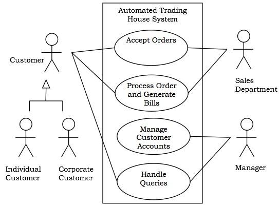
For instance, from the diagram below, the trading house contains transactions with corporate and individual customers, once the client places the order, the sales department processes it where he or she gets the bill. Therefore, the system enables the manager to plan clients account and answer any questions posted by the consumers.
The figure of Use Case diagram
Functions activity diagrams
The diagrams describe the flow of the activities that undergoes the operations of the state machine. These activities may lead to the atomic operation actions. They are also used to model workflows, mainly when the actors interact with the system and even in modelling the details of computations and operations using flowcharts (Gulia & Choudhury, 2016).
Categories of the activity diagram
Objects
Transitions
Action and activity state
Software processing that accomplishes the workflow
Initial activity implies the stating state where the activity is depicted in the original state. A process uses a black filled circle to detect the initial conditions of the system. For example, in UML activity model, it marks the initial and entry point of the activity state.
Activity shows the representation of actions execution on the objects. It may represent an activity by incorporating rounded corneas rectangle where an activity may represent an action.
The decision is made using the node before the flow of control is decided. For example, a diamond may represent the decisions using alternative paths. Hence the outgoing alternatives may be indicated using guard or condition expression.
Signal concurrent activities
In this case, the fork node may be used in splitting a single incoming flow into various concurrent flows. It is indicated as a slightly thicker or straight line in an activity model. A joint node links different flows into a single flow, thus using join and fork mode together may be termed as synchronization (Kumar & Singh, 2015).
The final activity is the state where the system reaches, or activity ends and is termed as the end or final state. The filled circle may be used to represent the machine diagram state.
The figure of the activity diagram

Precondition (TBD)
Three Sequences (TBD)
Incoming Message to the Sequence (TBD)
Precondition (TBD)
References
Chikurtev, D., Yovchev, K., & Chikurtev, E. (2016). Design and functionality of the web user interface for control of service mobile robot through the Internet. Problems of Engineering Cybernetics and Robotics, Sofia, 67, 51-60.
Gulia, S., & Choudhury, T. (2016, January). An efficient automated design to generate UML diagram from Natural Language Specifications. In 2016 6th International Conference-Cloud System and Big Data Engineering (Confluence) (pp. 641-648). IEEE.
Jones, P. A., Clothier, J., & Jiang, X. (2018, December). DigiView: connecting digital resources to the physical sphere through embedded library interfaces. In Proceedings of the 30th Australian Conference on Computer-Human Interaction(pp. 506-512). ACM.
Kumar, B., & Singh, K. (2015). Testing UML designs using class, sequence and activity diagrams. International Journal for Innovative Research in Science and Technology, 2(3), 71-81.
Laakso, K. P., Husu, T., Romppainen, M., Fagerlund, J., Kettunen, M., & Standell, T. (2016, May). User Interface Design In Agile Projects. In Proceedings of the 2016 CHI Conference Extended Abstracts on Human Factors in Computing Systems (pp. 1007-1010). ACM.
Laudon, K. C., & Laudon, J. P. (2016). Management information system. Pearson Education India.
OGGIONNI, M. (2018). Be pleasurable, be innovative. The emotional side of design thinking.
Pathak, K., Sharma, D. K., Bhalla, V., Jain, A., & Lad, M. (2018). Design and development of a graphical user interface for remote monitoring and control of the RF system. In Proceedings of the eighth DAE-BRNS Indian particle accelerator conference.
Petsas, T., Tsirantonakis, G., Athanasopoulos, E., & Ioannidis, S. (2015, April). Two-factor authentication: is the world ready?: quantifying 2FA adoption. In Proceedings of the eighth european workshop on system security (p. 4). ACM.
Song, W. (2017). Requirement management for product-service systems: Status review and future trends. Computers in Industry, 85, 11-22.
Stevens, P., & Pooley, R., (2016). Using UML: software engineering with objects and components. Addison-Wesley Longman Publishing Co., Inc.


