Detail-level technical architecture definition requires the generation of various types of diagrams. These diagrams are created using a standardized modeling notation. Just as BPMN is used as the nota
Running head: BUSINESS ARCHITECTURE MODELING 1
Business Architecture Modeling
Artifact Analysis and Design
Both the analysis and the design of business artifacts are crucial for the operation of the AAF virtual business. Business Process Modeling Notation (BPMN) together with Unified Modeling Language (UML) are useful in modeling business processes. However, in recent times, the BPMN has found prominence over UML, since it is more focused on the hierarchical nature of the business process while UML is more of a programming tool. For one to understand the AAF business process and artifacts presented in week 4, they will need to use the BPMN tool to represent the business process as represented in the context diagram, the system model and the information model. The relationship between events and activities will be well understood using the BPMN representation than simply using the models and the context diagrams developed in the previous sections. The BPMN for the organization will be as represented below:
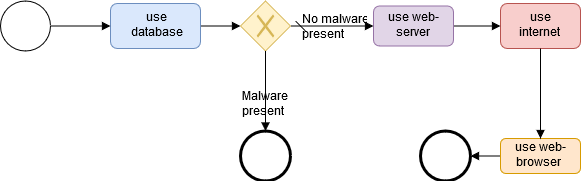
Figure 1: System BPMN Diagram
As explained in the previous tasks, this system diagram will provide a representation of both the end-users and the developer’s views. This diagram will present the sequence of flow from the inner system, the database to the user interface, which will be presented in the form of a BPMN diagram. This will be helpful for anyone as it will help them understand the flow of sequence for the system, especially for those interested users and the developer. It might be useful in developing other systems like this for the developer. It will also help the developer is planning for the system by making it easier for him/her to identify risks even before they happen and thus help in the process of mitigating them.
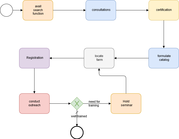
Figure 2: Information BPMN Diagram
The information BPMN diagram provides the sequence of flow of information in the AAF. This will be useful in helping the organizational farmers and stakeholders to understand the system of information flow within the organization. Through the system of information flow, it will be possible for any risks which occur during these tasks to be identified and addressed in advance to avoid a scenario whereby the organizational operations will be affected by the risks. The technical requirements which were discussed in the week 4 section will also be well achieved and analyzed by using the information BPMN diagram.
Decision Rationale
As seen from above, various notations are used in the BPMN. First, there is the use of a sequence flow. This is represented by the notation of a solid line that has an arrow at the head. This is very useful in showing the activities which have been performed in the BPMN diagram. Using the sequence flow notation, one can easily tell the order of the activities in the BPMN diagram. It presents a good visual representation of this. In addition to this, the BPMN diagrams, in this case, have a slash sequence flow, represented by a slash at the start of the solid line with an arrowhead. This shows the default flow. The decision or activity which will be taken in the case that there is a condition. This will mainly happen in the instances whereby the conditions to be satisfied by both sequence flows are not meant. This was used in instances where there was exclusive decision making.
Events are also other notations used in the BPMN diagrams above. There are two events in this case which have been used, the start and the end event. Events in BPMN diagrams are represented using a circle (Chinosi, & Trombetta, 2012). Events denote that something has happened. Though the event might be modified to represent the type of event, by having icons within the circle, the ones used in this case were representations for both general start and general end event.
The BPMN diagrams above used one gateway. This was the exclusive gateway. This is a gateway that is used to create alternative flows for the process. This is represented by the diamond with an X inside. The exclusive actions, in this case, means that only one action can be taken at a time and not both. Also, there is a default sequence flow which will be mainly used in case there is no condition that needs to be satisfied by the flow. The use of this in the BPMN diagrams above was where there was a need for choosing between two flows of sequence at a time and thus it was necessary.
Finally, activity notations were also used in the BPMN diagrams above. This described the kind of work that is performed or that must be done. In other words, this represents the work to be done. In this case, one can see that the activities are all given the same notation and have their sequence developed by using the sequence flow and default flow. The activities use in this case are the tasks, which is the lowest level of activity as it cannot be broken down any further. This notation is represented using a rectangle with a rounded-rounded corner (Wong, & Gibbons, 2008, October). All the activities, in this case, are tasks. The choice of this was because the models used represented the smallest level of activity.
BPMN Alignment with Reference Architecture
This model was developed from the reference architecture. One can see that most of the tasks in the BPMN diagram are developed from the previous reference developed in the fourth week of the course. All the tasks in the BPMN diagram are like those in the information and system models. This shows that the two are aligned together. The only difference between the two diagrams is how the two models are developed. One model is only representing the activities without a clear representation of the flow sequence. This is something that is well represented in the BPMN diagram. As such, the BPMN diagram represents a clear view of how activities and tasks, in this case, are ordered. This is very useful for all stakeholders as it makes it easier for them to track all the requirements and see if they are met.
References
Chinosi, M., & Trombetta, A. (2012). BPMN: An introduction to the standard. Computer Standards & Interfaces, 34(1), 124-134.
Wong, P. Y., & Gibbons, J. (2008, October). A process semantics for BPMN. In International Conference on Formal Engineering Methods (pp. 355-374). Springer, Berlin, Heidelberg.


