I will Attach 4 things below, 1- the lab manual, but since we don't have the tools there is an alternative way you can use to get the data easily. I will attach the alternative below, it is the "Added
Temple UnivERSITY PHYSICS
Ohm’s Law
The current through a resistor is proportional to the voltage across the resistor. This simple relationship between three fundamental electrical quantities current, voltage, and resistance was named Ohm’s Law after it’s discoverer to commemorate this extremely useful contribution to science and engineering. It’s important to note that Ohm’s Law holds for resistors and conductors, so-called ohmic materials, but there are also non-ohmic materials such as electric heating elements and semiconductors.
Current, voltage, and resistance, are somewhat abstract concepts because we can’t directly observe the electrons flowing through a wire. To help with our understanding, we can make an analogy between electron flow and something more familiar to us in everyday life: water flow. While pressure drives water through pipes, voltage drives electrical current through wires. The table below shows the electrical quantities and their water analog.
| Electrical Quantity | Description | Units | Water Analog |
| Voltage | The potential energy difference per unit charge between two points in a circuit. | Volts (V) | The pressure difference between two points in a pipe. |
| Current | The charge per second passing through an element. | Amperes (A) | The flow rate (i.e. liters per second) through the pipe. |
| Resistance | Resistance to charge flow through an element. Resistance reduces charge flow unless voltage is increased. | Ohms () | A constriction in the pipe that reduces flow unless pressure is increased. |
Learning Goals for This Laboratory:
Learn how current, resistance, and voltage are interrelated.
Practice connecting complete circuits and evaluating current flow.
Apparatus
iOLab device with dongle and software installed, wires, several 1 Ω and 10 k Ω resistors, breadboardThroughout this lab we will be using our iOLab devices to measure voltages in different places on a few simple circuits. You may want to review the previous lab on the basics of the breadboard and iOlab. If you get your resistors mixed up and do not know how to tell them apart, check out this guide to reading the color bands http://www.resistorguide.com/resistor-color-code/
Part I. Measuring the current in a circuitThe general procedure is to build a simple circuit and use an ammeter ![]() to measure the current through the circuit. The circuit, shown in Figure 1 below, is simply a 10 kΩ resistor connected to a 3.3 V voltage source. Note that 10 kΩ is only the nominal value of the resistance, the actual value is usually slightly off due prioritizing cost over precision.
to measure the current through the circuit. The circuit, shown in Figure 1 below, is simply a 10 kΩ resistor connected to a 3.3 V voltage source. Note that 10 kΩ is only the nominal value of the resistance, the actual value is usually slightly off due prioritizing cost over precision.

Figure 1. Simple circuit with 3.3 V source, 10 kΩ resistor and ammeter.
Current measurements are done using ammeters, so named because current is measured in amps. Ammeters don’t measure current directly, instead they are comprised of an internal resistor and voltmeter. If we know the voltage across the internal resistor, we know the current through it via Ohm’s law. Figure 2 shows the same circuit as Figure 1 with the ammeter’s internal resistor and voltmeter shown within the dashed box. As you can see, our ammeter is simply a 1 Ω resistor added in series to the 10 kΩ resistor along with a voltmeter connected in parallel across the 1 Ω resistor.
Figure 2. Circuit showing composite parts of the ammeter inside the dashed line.

Question 1. What is the current in units of mA flowing through a 1 Ω resistor if it has 5 mV across it? What is the current when the same resistor has 10 mV across it? How about 100 mV? Do you see the trend here (and why we chose a 1 Ω resistor for our ammeter)?
On your breadboard, build the circuit in Figure 2. Leave out the voltmeter until the last step. There are a lot of ways to connect this circuit on the breadboard, one way to do it is as follows:
Start by connecting a wire from iOlab’s 3.3 V output to the positive power rail of the breadboard.
Then connect one end of the 10 kΩ resistor into the positive power rail and connect the other end into a pin of your choice on the breadboard.
Next, connect one end of the 1 Ω resistor into the same row as the 10 kΩ resistor, and the other end of the resistor into the negative power rail of the breadboard.
To complete the circuit, use a jumper wire to connect the negative power rail of the breadboard to the ground (GND) of the iOlab.
Your circuit should look something like this:
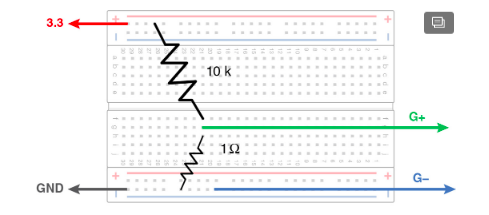
Figure 3. Example breadboard layout for measuring the current through a 10 kΩ resistor. Note that both resistors and the G+ jumper all connect to the same row of the breadboard.
The last step is to connect iOlab’s high gain G+/G- sensor as the voltmeter. Use two wires to do this, one for G+ and one for G-, and connect one to each end of the 1 Ω resistor as in the figure.
Question 2. Before taking measurements, calculate the current expected in this circuit. Note that because the circuit is a single loop, there is only one value of current shared by all components in the circuit.
Question 3. Will we introduce significant error if we ignore the 1 Ohm resistor when calculating the current in this circuit? Why or why not? Back up your answer mathematically noting that resistances in series add, so the total nominal resistance is 10,001 Ω.
In the iOLab software, select the High Gain sensor and click Record to see the data displayed in real time. If you obtain a negative value for the voltage across the 1 Ω resistor, you probably reversed the G+ and G- jumper wires. If your data is noisy, check your jumper wires for loose connections. If you’re having trouble viewing the data, you can use the set of three buttons next to the Reset button. The first of these buttons allows you to see the exact values of data points at the location of your cursor. The second button with the dropdown allows you to zoom in along the x- or y- axis or both. The third button allows you to click and drag the data around however you like (this is especially helpful if the data goes offscreen).
Convert the high gain sensor’s voltage measurement to current in units of mA. Make an Excel table with columns for voltage, current, and nominal resistance and record your values in the table (the voltage is 3.3 V). Compare the current you measured to the expected value and find a percent difference.
Does it matter whether the current is measured upstream or downstream of the 10 k Ω resistor? Try swapping the resistors and measuring the current to confirm that in a circuit with a single current loop the order of the components doesn’t matter, and the current is the same everywhere in the circuit.
There is a range of tolerance (i.e. a margin of error) associated with most resistors when they are manufactured. Check the resistor color code chart linked above and determine the tolerance of the 10 kΩ resistor (usually the tolerance bands are brown (1 %), gold (5 %), or silver (10 %)). Add a fourth column to your data table for actual resistance in Ω. Use the known voltage of 3.3 V and the current you measured to have Excel calculate the actual resistance.
Question 4. Does the measured resistance fall within the tolerance range of the nominal value of 10,000 Ω? For example, if the tolerance of a particular 100 Ω resistor is 10 %, the actual value should be in the range 100 10 Ω. If the value is not within this range, the resistor is “out of spec” and could be returned to the manufacturer.
Part II. ExplorationLet’s add to our circuit and further explore Ohm’s law along with series and parallel circuits.
What will happen to the current flowing in our circuit if we add more resistors in series? Add a second 10 kΩ resistor in series with the first so that you have the circuit in Figure 4 below. What do you think the current will be now? Measure and record the new current and corresponding nominal equivalent resistance for this circuit in the data table with your values from Part I. Remember that for series resistors, the equivalent resistance is the sum of all of the individual series resistances. Also calculate the actual resistance for your table.

Figure 4. Measuring the current with two 10 k resistors in series.
Add one of the 4.7 kΩ resistors in series to your circuit so that you now have two 10 kΩ and a 4.7 kΩ resistor in a single circuit. Record the current, nominal equivalent resistance, and calculated actual resistance in your data table.
Finally, add the other 4.7 kΩ resistor in series so that you now have two 10 kΩ and two 4.7 kΩ resistors in a single circuit. Record the current, nominal equivalent resistance, and calculated actual resistance in your data table.
Now let’s build a circuit with two parallel 10 kΩ resistors as in Figure 5 below. Add 1 Ω resistors to each branch of the circuit so we can measure the current in each branch. Use the high gain leads as before to measure the voltage on the 1 Ω resistors; for convenience you only need to touch the leads to either end of a 1 Ω resistor rather than plugging the leads into the breadboard. Compare the current in each of the three branches of the circuit and record the values for your lab report.

Figure 5. Two 10 kΩ resistors in parallel. Several 1 Ω resistors are added for current measurement.
Question 5. Find the equivalent resistance of the circuit having two parallel 10 kΩ resistors (remember parallel resistors add in inverse, refer to your text if you are unfamiliar with equivalent resistance of parallel resistors). Does the current you measured in the series resistor (the bottom one in Figure 5) roughly agree with what is expected according to the equivalent resistance you calculated?
Question 6. What current did you predict should be flowing in each branch of this circuit? Why is this current the same as when you had only a single 10 kΩ resistor in the circuit? Support your answer mathematically using Ohm’s law.
0


