Answer the attached document
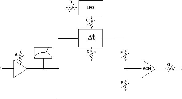
The block diagram below describes the signal flow within a digital delay device. The user operates the device via seven rotary controls, labeled A through G. Delay is provided by the module labeled t. The LFO is a low frequency oscillator that generates a sine wave, which can be used to continuously increase and decrease the delay time.
a. Which level control should be used to adjust the output level from the device? Explain.
b. How would you adjust the balance between the delayed signal and the non-delayed signal? Explain.
c. Which controls affect the audio signal level? Explain.
d. Which control should you adjust to set a fixed (nonvarying) delay time? Explain.
e. Which control adjusts the frequency of the LFO? Explain.


