Homework assignment
Logical Network diagram
John Padgett
NTC/ 248
January 31, 2017
Robert Chow
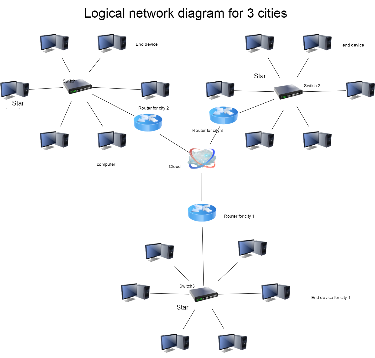
Explanation of the logical network diagram
In the above diagram I used various symbols contained in the Microsoft Visio to show how the network will look like in the three cities and how the connection will be in the cities networks and how the different cities will have connected with each other. In the individual cities I have used star topology where the switch is the central device connecting the other devices in the network. This is because it is easier to implement and troubleshoot (Maxwell, 2015).
The following table show how the different devices are working and how they were chosen in the connection of the network.
| Device | vendor | Its use |
| Router | CISCO | Connecting the three different cities network’s together so that they can communicate effectively |
| Switch | CISCO | Connecting the end devices such as computers, printers and scanners as well as connecting to the router |
| cables | Cat 6 cabling | They are the media for signal transfer from one device to the other |
| End devices | HP and Dell | They are used to perform the day to day operations in the three cities organizations. They include computers, printers etc |
Reference
Maxwell, J. (2015, June 5). Star Topology. Retrieved from Computer hope: http://www.computerhope.com/jargon/s/startopo.htm
CCNA: Network Media Types > Twisted-Pair Cable - Cisco Press
www.ciscopress.com/articles/article.asp?p=31276


