Modern Computer Architecture - Memory and I/O Systems
9
Introduction
In this assignment, IP, we will execute the implementation of Direct Memory Access (DMA) module. Direct Memory Access allows the peripheral devices to move information from or to memory without having the processor handling each byte. Thus, DMA enables more efficient use of interrupts, increases data throughput, and potentially reduces hardware costs by eliminating the need for peripheral-specific FIFO buffers. This makes DMA an important module for any System-on-a-Chip as it can increase performance by a large factor. In this project, we will implement a DMA controller and interface it with the ARM processor. We will then evaluate the gain in performance of our complete SOC system with the DMA. We will do this by running a very data intensive test program which has a high frequency of memory accesses.
GENERAL DESCRIPTION OF A DMA
Direct Memory Access (DMA) is a well know technique, whereby an I/O device gets
access to memory directly without having the microprocessor in between. By this direct
path, a word input through a device, can be stored in memory, or a word from memory
can be output through a device, on the device’s request. It is possible for a word in
memory to be moved to another place in memory using direct memory access.
DMA is one of the fastest ways to input data to a buffer. This technique requires
considerably more hardware and is considerably faster than if it were done through
software. A DMA channel is the additional logic needed to move data to or from an I/O
device.
FUNCTIONAL SPECIFICATIONS
The following is a description of how our DMA controller works [2]:
1) The CPU initiates the transfer by supplying the following data to the DMA controller: the memory address of the source and destination of the data to be transferred, and the number of bytes to transfer. The CPU does so by writing this data to the DMA internal registers (shown later).
2) The DMA controller starts the operation on the device and requests the bus. Once the bus is granted to DMA, it then waits on the Source Device to provide data. When the data is available, it transfers the data to the destination. The DMA controller supplies the memory address for reads and writes. If the request requires more than one transfer on the bus, the DMA unit generates the next memory address and initiates the next transfer.
3) Once the transfer is complete, the DMA controller interrupts the processor and notifies it if there were any failures during the transfer. Note that the processor has to wait for the DMA to finish the transfer before it can supply it with the next transfer. Therefore, the processor has to keep track of transfer requests and transfer acknowledgments. This is accomplished using a dedicated control port connecting the DMA to the AMBA Bus and thus to the processor.
IMPLEMENTATION
Hardware
In this project, we used the tools we learned in this class to complete this project. First, we
used The Platform Creator from Coware to draw a system level diagram (Figure 2). We
developed the following two hardware modules in SystemC.
1. A DMA controller (block level diagram shown later as Figure 3)
2. A disk
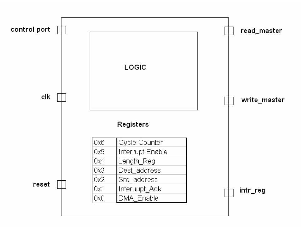
Block level
diagram of DMA
Controller.
The Internal Register
File can be seen
ARM Core Software
Another important task in this project was to develop a program that can be used as a test
program. We wanted this program to be a realistic application of the DMA. We provide a
description of this program in the next section.
Interface
We used the AMBA API to interface the modules with the existing system. There were
two master ports and one slave port that we added to the AMBA bus as a part of the
DMA controller. Similarly, a Slave port was also added to the AMBA bus for the disk.
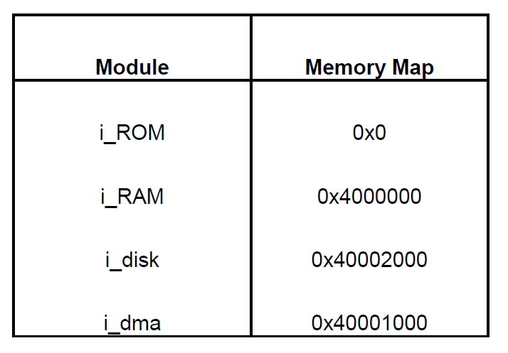
The interfacing was done using memory-mapped I/O. The following table shows the
memory map table of the system. The DMA port shown here is a slave that is used by the
processor as the control port to program the DMA controller for transfers.
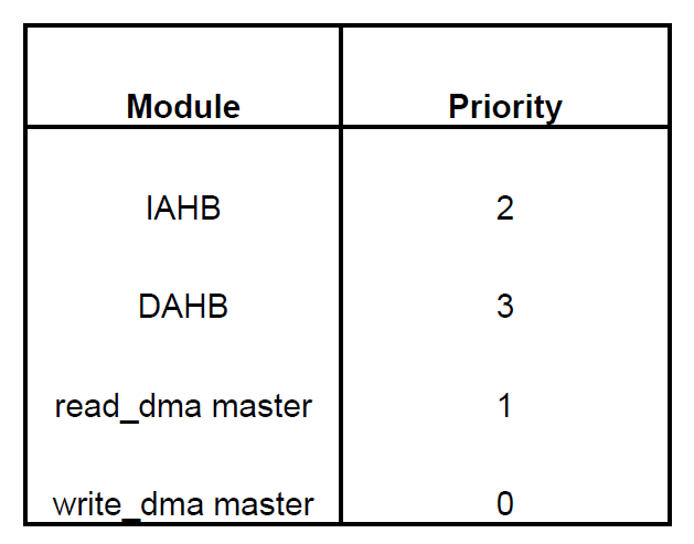
Another important portion of the interfacing involved the arbitration of the bus between
the 4 AHB initiators. (two from processor and two from the DMA). We used a fixed
priority arbiter from the AMBA library to handle this issue. The fixed priorities were
assigned by us as the program specifications. The following table shows the priorities
assigned to each AMBA initiator in the system.
PERFORMANCE EVALUATION
To evaluate the performance gains of the DMA module we developed a data intensive
test program with a high frequency of memory accesses. The test program is basically a
small Kernel that computes the dot product of two vectors A and B. Both vectors are
stored in the disk and the processor first has to retrieve them and put hem into the RAM
before it can start performing the computation. Since both vectors are very large, the
processor brings them into the RAM one part at a time. Each part is referred to as a page.
This is basically to mimic the working of a complete operating system with the Virtual
memory translation enabled. The pages are brought into the RAM on-demand. This
demand driven process allows the processor to work in the foreground while the DMA
can transfer the page in the background.
We first run this program without the DMA and count the total number of cycles the
program takes to execute. We then repeat the experiment with the DMA. In this version
the processor instructs the DMA to load the subsequent pages of the vectors while it
works on the current page. The processor keeps track of which pages have been moved
into memory using a score boarding technique to ensure that it only computes valid data.
That is, it makes sure the page has been transferred before it tries to use its’ values. Each
time the DMA interrupts the processor signaling that a transfer has been complete; the
processor requests it to fetch the following page. This way the processor works on the
data that has already been transferred into the memory while the DMA fetches the rest of
the data.
We performed this experiment several times while varying the disk latency. We wanted
to see how the disk latency affects the performance boost of the DMA. Finally, we
measured the number of cycles the processor sits in an idle state waiting for the data. This
analysis was done for a latency of zero cycles.
CONCLUSION
In conclusion, we successfully implemented a DMA module in SystemC. We successfully
demonstrated the gains in both processor utilization and total number cycles with the use
of a DMA controller. It is important to note that these gains can only be realized if the
application is data intensive and has very high frequency of memory accesses. An
important result that we found was that the DMA’s effectiveness diminishes as the Disk
Latency increases.
REFERANCES
http://www.embedded.com/showarticle.jhtml?articleid=15300200, April 2005.
John L. Hennessy and David A. Patterson. Computer organization and design (2nd ed.): the
hardware/software interface. Morgan Kaufmann Publishers Inc., San Francisco, CA, USA, 1998.
G. Jack Lipovski, Embedded Microcontroller Interfacing for M. CORE Systems. Academic Press, 2000
AMBA Bus manual provided at coware1.ece.utexas.edu:/usr/local/packages/coware/convergencesc/documentation/AMBA_BL
ARM926EJS manual provided with the coware documentation at: coware1.ece.utexas.edu:/usr/local/packages/coware/convergencesc/documentation/ARM926EJS_AHB_PSP.pdf
ARM DMA specifications provided in the ARM Coware library documentation


