Need help with the attached assignment please............YOU MUST KNOW HOW TO USE LOGIXPRO PLC SIMULATOR TO COMPLETE IT!!!!!!!
Unit 5 Lab Assignment: Developing Fundamental PLC wiring Diagrams & Ladder Logic Programs
Lab Objectives:
Develop ladder logic programs based on operational requirements.
Use different instruction methods and addressing to perform specified tasks.
Prelab requirements:
Before starting the lab assignment, complete the following:
Make sure you can access the LogixPro PLC Simulator. The simulator is available on the local classroom PC. You can also access the LogixPro PLC Simulator via the XenDesktop. Instructions to access the XenDesktop is available under Course Foundations section of this course.
To familiarize yourself with the software, read and work through the "Getting Started with RSLogix and LogixPro". This document is also available at the beginning of the Lab Manual.
Lab Instructions:
This lab is comprised of two parts. All parts are available in your lab manual, but for your convenience, they are also included below. All parts will use the LogixPro PLC Simulator.
General Requirements for all Parts:
For each program you develop, make sure that your name is added as a comment to rung 0 followed by the file name such as ‘Lab 1-1’.
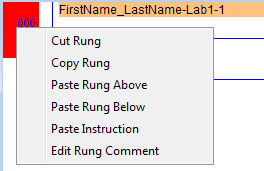
Select the rung and hit right-click. You should get the options shown below.
Choose ‘Edit Rung Comment’ and enter your name followed by the lab number as shown below.

You must provide appropriate instruction symbol/name for each instruction used in your ladder logic program, e.g.,
Part I:
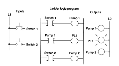
Complete Assignment 13-2 shown below; it is also located in chapter 13 of your lab manual.
| 13-2 With reference to the ladder logic program shown, add instructions to modify the program to ensure that Pump 2 does not run while Pump 1 is running. If this condition occurs, the program should suspend operation. Use the I/O Simulator screen and the following addresses to simulate the program: Switch 1 _ I:1/0 Switch 2 _ I:1/1 Pump 1 _ O:2/0 PL1 _ O:2/1 Pump 2 _ O:2/2
(Petruzella, Frank. LogixPro PLC Lab Manual for Programmable Logic Controllers, 5th Edition. McGraw-Hill Learning Solutions, 1/2016. VitalBook file. |
Save this program as EET231L_U5_Lab1-1_FirstNameLastName.rsl.
Part II:
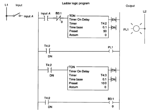
Complete Assignment 13-3 shown below; it is also located in chapter 13 of your lab manual.
| 13-3 The PLC program shown is supposed to execute to sequentially turn PL1 off for 5 seconds and on for 10 seconds whenever input A is closed. Troubleshoot the circuit, and identify what needs to be changed to have it operate properly. Use the I/O Simulator screen and the following addresses to simulate the program: Input A _ I:1/0 PL1 _ O:2/0 Internal Relay _ B3:1/0 Timers _ T4:2 & T4:3
Petruzella, Frank. LogixPro PLC Lab Manual for Programmable Logic Controllers, 5th Edition. McGraw-Hill Learning Solutions, 1/2016. VitalBook file. |
Save this program as EET231L_U5_Lab1-2_FirstNameLastName.rsl.
Submission Requirements
You are required to submit the following:
All LogixPro files (*.rsl) for the parts of the lab following the proper naming convention.
EET231L_U5_Lab1-1_FirstNameLastName.rsl
EET231L_U5_Lab1-2_FirstNameLastName.rsl
One document outlining the following:
Program flowchart or needed truth table(Visio can be used to develop the flowchart)
Input and Output table
Your Lab Assignment will be graded according to the below marking guide.
Marking Guide
| Sections | Points | Criteria | Ratings | |
| Full Marks | No Marks | |||
| Overall Format | Name is added as a comment to rung 0 followed by the file name such as ‘Lab 1-1’ for each submitted program, e.g., | 5 points | 0 points | |
| Appropriate instruction symbol/name for each instruction used in the ladder logic program, e.g., | 5 points | 0 points | ||
| Part I | 45 | Proper program commenting and labeling | 5 points | 0 points |
| Design Methodology | 15 points | 0 points | ||
| Correct Functionality according to specifications | 25 points | 0 points | ||
| Part II | 45 | Proper program commenting and labeling | 5 points | 0 points |
| Design Methodology | 15 points | 0 points | ||
| Correct Functionality according to specifications | 25 points | 0 points | ||


