two lab assignments
Electric Fields and Gauss’s Law
Online Instructions
OBJECTIVESTo understand how electric field lines can be used to describe the magnitude and direction of an electric field in a small region of space.
To discover how the electric flux passing through a small area is related to the magnitude of the electric field, as well as the area and its orientation relative to the direction of the electric field.
To understand the relationship between the flux passing through a closed surface and the charge enclosed by that surface (Gauss’ law) for a two-dimensional situation.
To explore how Gauss’ law predicts where excess charge can be found on a conductor.
Coulomb’s law was used to calculate the force that two or more charges would have on each other. This force is considered a long-range force, one that happens at a distance. Thus, there is another way to describe this force using the notion of the Electric field. This model uses that the source charges alter the space around them such that they exert an electric force on some test charge. We describe this field by the magnitude and direction of the force on a positive test charge per unit charge. This force can be difficult to calculate using Coulomb’s law if there are many charges at different locations. It is possible to calculate this force with a different formulation of Coulomb’s law, known as Gauss’ law. Gauss’ law involves relating the net amount of charge inside a closed surface. This powerful tool is best used for calculating the electric field of situations where the charges are symmetric.
Activity 1: Simulation of electric field lines from point charges (40 points)Open the simulation “Charges and Fields”. Make sure that the Electric Field is unchecked, and that Grid is checked.
Set a single +1 nC charge in the middle of the screen.
Click and drag the sensor charge around to various points on the board.
Question 1: Describe your observations of the vector on the sensor charge. What is the general direction of the vector on the sensor charge? What happens to the vector when you move away from the positive charge?
Remove the positive charge by placing it back in the box. Now place a single -1 nC charge in the middle of the screen Click and drag the sensor charge around to various points on the board.
Question 2: Describe your observations of the vector on the sensor charge. What direction does the vector generally point and how does the vector change the further they are away from the negative point charge?
Place a positive charge on the left side of the screen and a negative charge on the right side of the screen roughly 600 cm apart in the simulation. You can use the measuring tape tool and that each square in the grid is 50 cm.
Using a grid or screenshot of the simulation make a sketch that you can later draw on. Make sure the positive charge is colored a shade of red and the negative charge a shade of blue.
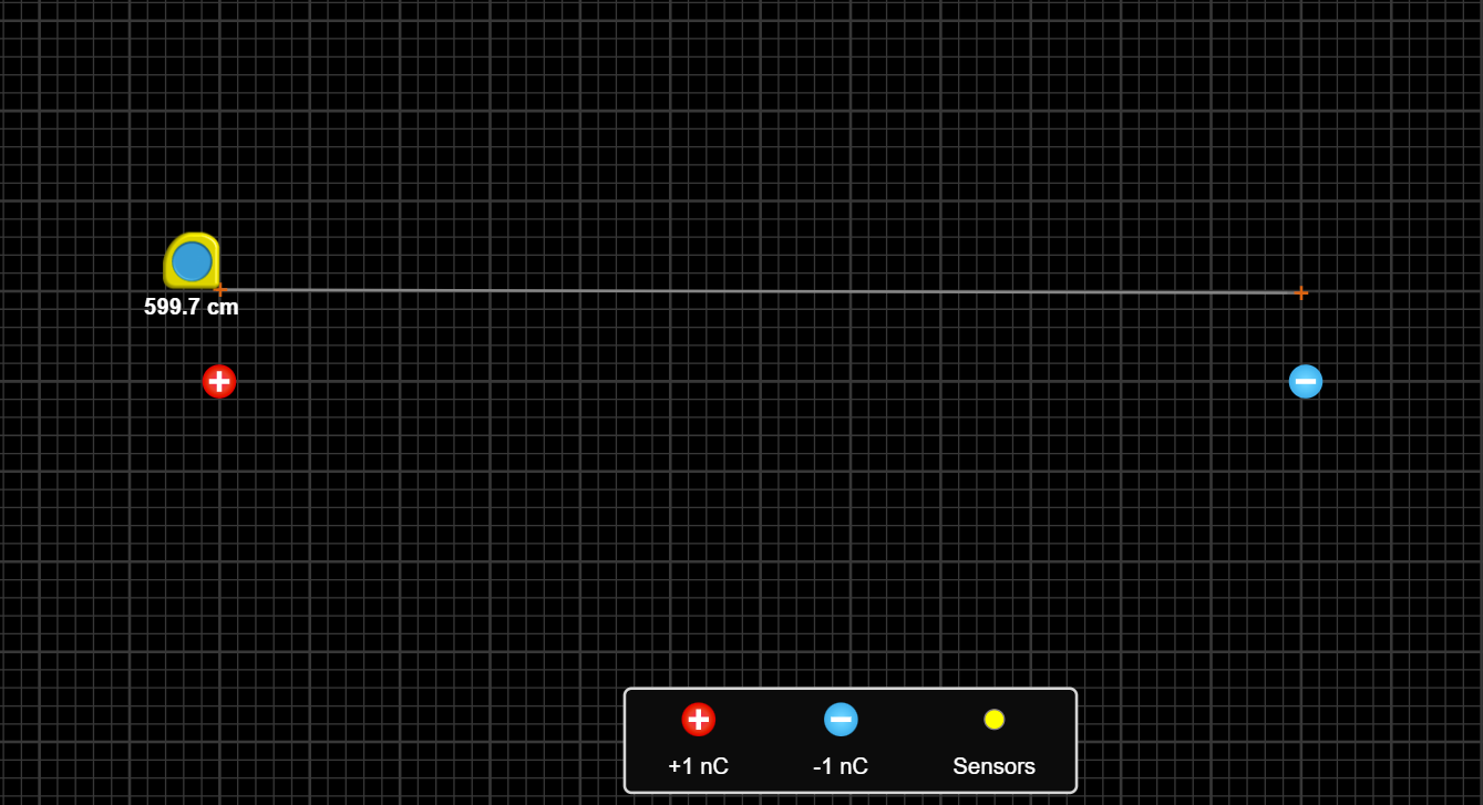
Using the voltmeter tool located on the right of the screen move it to various places between the two charges noting the change in the potential.
At 6 different points between the two charges, they must be at least 50 cm apart in the simulation, use the pencil symbol on the voltmeter to draw the Equipotential Line. On your drawing/sketch make the same line and label the voltage reading and distance from positive charge.
Using the sensor charge move it along the equipotential line closest to the positive charge.
Question 3: As you move the sensor charge along the line what do you notice about the relationship in direction of the force vector on the source charge and the direction of the line? Would you say they are parallel or perpendicular?
Question 4: Recall the definition of work as  . Using your answer from question 3, if you moved a charged particle along the line, would the electric field do any work on the particle? Explain.
On each of the Equipotential Lines use the sensor point particle to draw the electric force direction at 5 points along the Equipotential Lines, 2 above the line connecting the point charges, 1 along the line connecting the point charges, and 2 below the line connecting the point charges. The vectors should not be larger than 1/2 square (25 cm in the simulation). Make sure this is in a different color than the Equipotential Line color.
Starting from the positive charge draw a line, in the same color in step 10, that connects and follows the arrows towards the negative charge. These are your Electric Field Lines. You should have 5 lines, one for each of the arrows on the Equipotential Lines.
Question 5: Upload a picture of your sketch to answer this question.
Activity 2: Gauss’s law (20 points)Open the Electric Field Line Simulator.
Set the second charge to 0.
Change the value of the first charge from +1 to +5.
Question 6: What do you observe with the field lines as you increase the amount of positive charge?
Change the value of the first charge from -1 to -5.
Question 7: What do you observe with the field lines as you increase the amount of negative charge?
Question 8: What similarities and differences do you observe between positive charge and negative charges with their field lines?
This is a 2-D representation of what is happening in 3 dimensions.
We start by defining the Electric Flux as the amount of field lines passing through an area. This line is a 2-D representation of a loop, such as looking at ring from the side and not straight on.
The figure below is 2-D surface area next to a charge. Count the amount of field lines passing through at the various angles, The first is the normal at 0º with respect to the horizontal, the second is 45º, and the third is 90º.
![two lab assignments 2]()
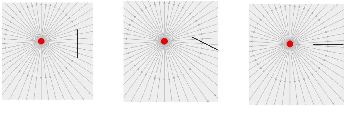
Question 9: What did you observe when the angle changed? If the line was longer would more lines pass through? If the charge was change would there be more or less field lines passing through?
Question 10: Write a mathematical relationship for flux based on your answer in Question 9.
On the simulation set the first charge to +1 and the second charge to -1.
Sketch what you see on the simulation.
Draw 4 arbitrary surfaces on your sketch. These arbitrary sketches must be closed surfaces and can take the shapes of circles, squares, triangles, or whatever you choose. These 4 surfaces must follow these rules; one must enclose the charge on the right, one must enclose the charge on the left, one must enclose both charges, and one must enclose none of the charges. They can be blobs, squares, triangles, circles, etc.
We will designate that lines that pass out of the boundary of your surface as a positive line. Lines that pass into the boundary of your surface as a negative line.
Copy the table, table 1, into your notes and fill the table out for each of your surfaces. The net charge and net lines you should add your positive and negative values. Remember that the amount of negative charge or negative lines are negative numbers. Example If there were 3 Positive lines and 2 Negative Lines the total amount of lines would be 3 – 2 = 1 line.
Table 1
| Surface | Positive charge enclosed | Negative charge enclosed | Net charge enclosed | Positive lines | Negative lines | Total amount of lines |
Question 11: What is the apparent relationship between the net flux (net number of lines) passing through an imaginary surface and the net charge enclosed by the two-dimensional surface? Explain, based on your observations.
Question 12: Express the three-dimensional form of Gauss’ law in words. To help you do this think, what would be the three-dimensional equivalent of the closed curves you drew? Does it still make sense in three-dimensions to talk about the net number of lines coming out of a closed surface?
Activity 3: Using Gauss’s Law (20 points)An electrical conductor has some of its electrical charges free to move about. If the free charge in a conductor experiences an electric field, it will move under the influence of that field. Thus, we can conclude that if there are no charges moving within a conductor, the electric field within the conductor is zero.
Figure 1
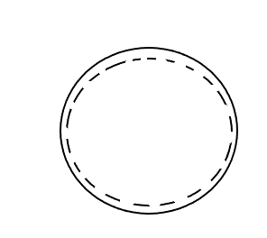
Question 13: If this neutral charged conductor is now given charge, where would the charge reside? Remember that the electric field inside the conductor must be zero.
Now consider the same conductor. It is neutral again, but this time it has a cavity, a hole inside that has a positive charge +q, inside. There are 3 gaussian surfaces; gaussian surface A encloses just the positive charge and resides inside the cavity, gaussian surface B encloses the cavity and resides in the conductor, and gaussian surface C encloses the whole conductor.
Figure 2
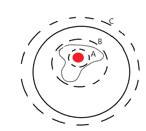
We developed that the amount of flux was equal to the amount of charge enclosed by the gaussian surface

Question 14: For gaussian surface A, how much charge is enclosed?
Question 15: Gaussian surface B is inside the conductor, which means that the electric field must be zero. If the electric field is zero, this also indicates that the electric flux is also zero. For this to be true what must be the net amount of charge enclosed? How would this be possible?
Question 16: Using your result from question 20, where must this other charge reside?
Question 17: For Gaussian surface C, which encloses the entire conductor, there is a positive amount of flux. Using what you gathered where must there be positive charge such that there is a positive amount of flux measured through this surface?
POST-LAB QUESTIONS (20 points)Describe the properties of electric field lines.
If the total number of lines leaving or converting on a charge doubles, what does that tell you about the magnitude of the charge?
What does the direction of a line at each point in space represent?
What does the density of lines represent?
Based on your observations of electric field lines, sketch several electric field lines originating from a +q charge. Then sketch several electric field lines originating from a +3q charge. The sketches don’t need to be exactly correct, but they should illustrate that you understand the properties of electric field lines discussed in question 1.
For the situations a through e, use the definition of flux that you developed in the lab to determine the electric flux passing through each surface. The electric field has a magnitude of 5.0 N/C at the location of the surface of area 0.0015 m2. Show your calculations.

What is the net electric flux through each of the closed surfaces? Each charge has a magnitude of q. Write your answer in terms of
 .
.
Figure 3
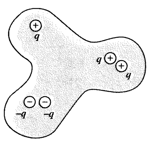
Figure 4


