electronic engineering. level 3( includes robotics and legislation)
|
I confirm that all the work in this coursework is my own. | Student Signature. | Date. |
| 03-03-17 |
 Student Declaration on Submission
 | General Feedback by Tutor Fair work, tasks 1 & 2 are fine, update tasks 3 & 4 You can optionally correct the merit tasks 5-7. See feedback comments attached Please return within 10 working days and remember to attach your corrections to the bottom of this document, and don’t change any of the original work 11/3/17 |
| Sampled by IV: Sign | Date: | 03-03-2017 |
Assessment grading instructions:
Tasks 1 to 4 are required for PASS (P) grade and must be attempted
Tasks 5 to 7 are required for MERIT (M) grade
Tasks 8 is required for DISTINCTION (D) grade.
Work for Merit/Dist grades should also be supported by fully referenced evidence
Tasks for Assessment 2 (2 of 2)
All answers must be your own worK
Note: Copy and paste these cover and task sheets to the front of your written work as you must sign (electronic signature) and date these in order to have your assessment marked and graded
Task 1 [P1]
The Maintenance Manager has asked you to review the planned maintenance (PM) procedure for 2 pieces of equipment in the factory. The 1st piece of equipment is a 50m conveyor used to transport product in a cleanroom between process steps. The conveyor also contains a number of elevators protected by guarding. The 2nd piece of equipment is a mixing tank agitator driven by an induction motor controlled by an inverter. The tank is made of stainless steel and contains acidic chemicals when in use.
As part of the review you will need, for each apparatus, to explain and identify the hazards that exist when a planned maintenance (PM) is being carried out. These are risks posed to anyone in the area, not just the Technicians carrying out the PM. In particular focus on electrical hazards
Task 2 [P2]
From the information in task 1 you must also specifically list the control measures required to eliminate or manage the risks to the Maintenance Technicians and others. In particular give a detailed range of control measures to prevent/reduce the risk of electric hazards
Task 3 [P3]
A quality and safety audit is to be carried out on all the maintenance procedures in the factory. The Maintenance manager has asked you with reference to at least 4 pieces of safety legislation, regulations or standards, and how these might apply to the PM activities described in task 1
Task 4 [P9]
From the audit you have been asked to draw a start/stop/retain relay control circuit that could be used for the safe and emergency operation of a 3-phase drilling machine and lathe in the workshop that must include 2 emergency stop positions. Also explain how the circuit would operate and what types of commercial relays/contactors could you select.
Task 5 [M1]
The production manager also wants your help in deciding the best type of motor system for controlling the speed of a new automatic conveyor line. He has asked you to explain with the aid of diagrams and research evidence, the operational features system for an AC drive system with variable speed control.
Task 6 [M2]
As an alternative to the AC system in task 5, you have also been asked to produce a circuit design that can control the speed and direction of the conveyor using a DC motor drive system. With reference to circuit layout drawings and research sources, explain how it operates.
Task 7 [M3]
A new robot cell has been installed to operate along with the conveyor system above. You have been asked to:
Describe with the aid of diagrams, the operation of a safety relay system used on a robot cell. (400 words)
Explain how this system addresses the hazards and control measures by also referencing relevant legislation, regulations or standards. (400 words)
Task 8 [D2]
To ensure that the conveyor system is safe and complies with legislation, compare the construction and operation of two different types of stop/start/retain relay control circuits for suitable for either the AC or DC system in task 5 or 6.
For example you may compare an electro-magnetic relay system with an electronic logic system. Include appropriate drawings, parts, truth tables and their advantages/disadvantages in your explanation.
Task 1 [P1]
The Maintenance Manager has asked you to review the planned maintenance (PM) procedure for 2 pieces of equipment in the factory. The 1st piece of equipment is a 50m conveyor used to transport product in a cleanroom between process steps. The conveyor also contains a number of elevators protected by guarding. The 2nd piece of equipment is a mixing tank agitator driven by an induction motor controlled by an inverter. The tank is made of stainless steel and contains acidic chemicals when in use.
As part of the review you will need, for each apparatus, to explain and identify the hazards that exist when a planned maintenance (PM) is being carried out. These are risks posed to anyone in the area, not just the Technicians carrying out the PM. In particular focus on electrical hazards
Conveyor
The common hazard is doing maintenance to a conveyor connected to power, air or hydraulic that has not been locked out, such as cut off valves not being closed, circuit breakers not being pulled/gagged and power not being isolated or given time to dissipate. As a result during working, a technician may accidentally close the guards or activate a sensor. The program running this conveyor may then start the conveyor. As a result of this, it could cause injuries to not only the maintenance crew but to people around the machinery.. If parts of the machinery have been taken off for maintenance an electrical hazard could potentially occur if cable looms or wiring becomes caught up in the workings of the conveyer leading to not only injuries to personnel but expensive and time consuming damage to the equipment.
Maintenance operations without all covers and guards open. This is a dangerous and poor maintenance practice because the guards and covers are there to protect the technician and personnel. If for example the conveyer is controlled by IR sensor sytem the technician could inadvertently block the beam which could then lead to the conveyer program commencing resulting in injury.
Loading a stopped conveyor. This is to eliminate overheating during starting. Overheating may lead to break down of insulation of the machinery wiring. This will cause a short circuit of power which may lead to a fire or electrical hazard.
Explosive Hazards. On a conveyer system this can occur this can occur due to poor ventilation which does not remove or filter the duct particles of the product being transported. Respiratory damage will also effect those working in an environment with poor ventilation.
Poorly laid out or insufficient emergency stops or cut off switches.
Nip points. which can easily draw in clothing, tools, loose hair, fingers or limbs, depending on the size, speed and power of the conveyor.
Static electricity damage to components- Many caused by mishandling and poorly stored equipment.
Faulty electrical equipment/ excessive extension leads.
Tank agitator
Never interchange the signals at the inverter. This is because the inverter may respond differently and drive the agitator in undesired way. This may cause even spillage of its acidic contents that may cause harm to personnel around.
Never alter the terminals of the motor. This will make it run in an opposite direction, if done without informing operators spillage of dangerous load.
Never allow motor terminals to come into contact with the acidic substance or water. As the two can conduct electricity. This may result to a short circuit resulting in a fire hazard.
Task 2 [P2]
From the information in task 1 you must also specifically list the control measures required to eliminate or manage the risks to the Maintenance Technicians and others. In particular give a detailed range of control measures to prevent/reduce the risk of electric hazards
Most importantly value of education, training, safe systems of work, power lock-offs and effective supervision should not be underestimated.
Positioning and selection of types of guards-It is highly likely that fixed guards (ie those requiring the use of tools for their removal) or movable guards will be chosen, depending upon the frequency with which access is required. For long conveyors, it is often not practical to interlock every movable guard due to the large numbers involved. In such situations, isolation procedures, safe working practices and rope-operated emergency stop controls have an important role to play.
Maintenance pionts installed-such as fitting remote grease points so that the conveyor can be lubricated without having to remove guards, and belt alignment mechanisms that can be operated from outside the guards. Guarding should also be designed, so far as possible, such that routine cleaning and clearing of spillages can take place without disturbing the guarding - such as by incorporating rodding access points.
Appropriate signs/ warning notices- during PM operations appropriate signs should be displayed informing personnel not to apply power or enter the work area.
Adequate air filtration/ ventilation- This will prevent build up of potentially explosive duct i.e coal particles.
Physical circuit breaker and power switch gags on a shadow board- this will prevent the system being left live and accidental application of power. By using the shadow board to keep them on it is an easy visual indication if they have not all been put in place.
Strict tool control system- again a shadow board system will ensure that all tools are accounted for after maintenance has been carried out. This will prevent tools being left in the machinery potentially causing a short circuit.
Tagging in system for personnel- During maintenance technicians are to tag into the work area and tag out on completion. Power is not to be applied nor is the machinery to be in any other way operated whist personnel are tagged in. This prevents potential hazards to technicians in the area.
Dual control powering system- For example two buttons far enough apart having to be pressed within 5 seconds of each other for power to be applied. This removes the danger of accidentally applying power and provides a second person to ensure it is safe to apply power.
Ant static wrist bands, rubber mats and correct storage for components- This will reduce the risk of static electrical damage.
Pat testing for all electrical items- This will reduce the risk of faulty electrical items entering or being used in the work area.
Task 3 [P3]
A quality and safety audit is to be carried out on all the maintenance procedures in the factory. The Maintenance manager has asked you with reference to at least 4 pieces of safety legislation, regulations or standards, and how these might apply to the PM activities described in task 1
It is important to ensure that a conveyor complies with the relevant standard and code of practice but the question of CE marking is a more difficult area. While there are some situations where a conveyor will be supplied as a standalone machine - and will therefore need to be CE marked - there are others where the conveyor needs a certificate of Conformity so that it can be incorporated within a larger machine that is then CE marked as a whole. If in doubt, seek advice from suppliers, consultants, or contact the HSE.
The goal is to ensure that the machinery is safe, so users should undertake a risk assessment and install the necessary safeguards to reduce the risks to an acceptable level.
Risk assessments should be carried out by qualified staff this will usually be the health and safety executive.
In line with general good practice, the objective should be to design-out hazards, rather than safeguarding them but, in reality, this is unlikely to be feasible where conveyors are already operating or have been purchased as off-the-shelf or configured-to-order units.
Since 1998, users of conveyors have been legally obliged to perform a PUWER assessment - which often reveals that existing safeguards are inadequate and that additional measures are needed. In addition, companies purchasing off-the-shelf, configured-to-order or custom-built conveyors frequently have to design and fit extra guarding. Elsewhere, companies are in a slightly better position if they build new conveyors in-house and are able to take safeguarding into account at the design early stage.
The PUWER 98 Regulations (Provision and User of Work Equipment Regulations, 1998) have already been mentioned, but there are several other regulations, standards and codes of practice that need to be considered. Three such examples are BS EN 620: 2002, 'Continuous handling equipment and systems - Safety and EMC requirements for fixed belt conveyors for bulk materials', BS 4531: 1986, ' Specification for portable and mobile troughed belt conveyors', and BS 7300: 1990, ' Code of practice for safeguarding of the hazard points on troughed belt conveyors.
Task 4 [P9]
From the audit you have been asked to draw a start/stop/retain relay control circuit that could be used for the safe and emergency operation of a 3-phase drilling machine and lathe in the workshop that must include 2 emergency stop positions. Also explain how the circuit would operate and what types of commercial relays/contactors could you select.
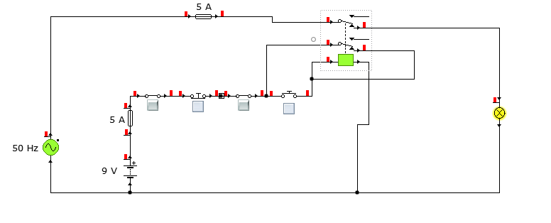
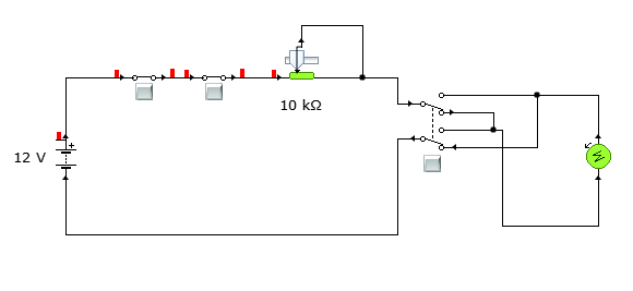
Safety is a major concern in a good many motor-driven applications. This is true in industrial applications where motion starts when power is applied and especially true when power is restored after an outage. In such cases, unwanted or unexpected motion is a risk to life or limb. The most simple solution to this problem is the simple, time-proven Run /Stop Relay Circuit.
With this control circuit, motion cannot commence (or restart) without the operator’s specific pushbutton command.
The control circuit draws 9V from the dc supply. It is first passed through fuse then first emergency switch. Then a stop switch is placed in series with the first emergency switch. Then there is the second emergency switch., activating either will open the circuit and de-energise the relay . Then there is a start push button. Its single action powers the coil of the relay. Therefore, the contact will shift down. Its output is looped back to provide a holding mechanism. Then the output is fed to the bulb but which in this case represents three phase relay or contactor coil. A Dc relay or electromagnetic relay would be suitable for this application.
Task 5 [M1]
The production manager also wants your help in deciding the best type of motor system for controlling the speed of a new automatic conveyor line. He has asked you to explain with the aid of diagrams and research evidence, the operational features system for an AC drive system with variable speed control.
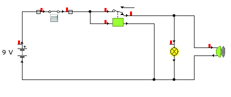
A three phase induction motor is best suited for this operation. This is because it is self-starting and it uses frequency of the supply to determine its speed. There should be in inverter circuit. Power inversion should be controlled by controlling the gate triggering so that frequency can be controlled.
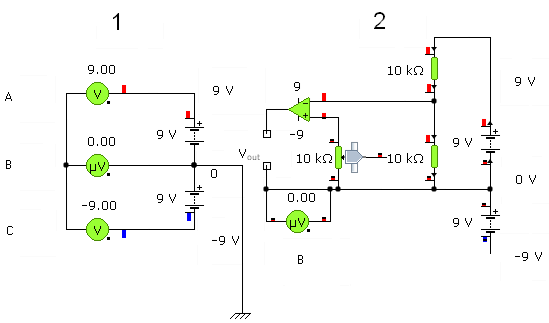
The circuit above shows a single phase inverter. The potentiometer used to vary frequency of the output waveform by adjusting how the capacitor charges and discharges. This circuit can be cascaded to generate a three phase inverter.
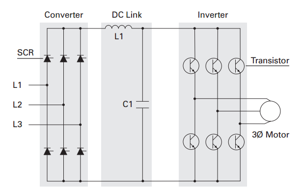
In a drive above. First the supply voltages are converted to dc voltages. Through the dc link, the inverter circuit receives dc power. With the help of a stored program, it is inverted into a desired variable frequency to be used by the motor
Task 6 [M2]
As an alternative to the AC system in task 5, you have also been asked to produce a circuit design that can control the speed and direction of the conveyor using a DC motor drive system. With reference to circuit layout drawings and research sources, explain how it operates.
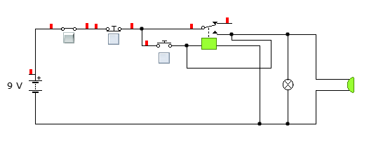
This circuit will contain an emergency switch, start latching button, potentiometer, double pole double throw switch and a motor. They will be arranged as shown below.
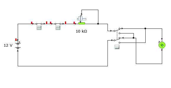
Power from the battery is passed through and emergency switch. It is then connected in series with the start button. An action of this two will either turn the motor on or off. A potentiometer is connected in series. This will be used to vary the speed of the dc motor by varying the supply voltage. Then a double pole double throw switch is connected in series to the circuit and lastly, the motor. DPDT is used to change the direction of motor rotation. And it is connected as above. When its selection switch is in a certain position, it rotates as show by an arrow above. When the position is changed, it will rotate as shown below.
Task 7 [M3]
A new robot cell has been installed to operate along with the conveyor system above. You have been asked to:
Describe with the aid of diagrams, the operation of a safety relay system used on a robot cell. (400 words)
A safety relay has an electromagnetic coil. The coil is only energized when powered. Once powered, it will act like a normal magnet and attract anything metallic near it. Hence, it will attract the contacts of the relay to close the circuit. When any guards or emergency or stop button is pressed, its supply power is cut, this will de-energize the electromagnetic coil. Hence, it loses its magnetic effect, releasing the contacts. This results to instant opening of the contacts of the relay

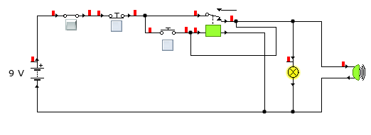
The circuit above show for an open control switch. This control switch can be a stop switch, emergency switch and even a sensor. When sensors are used for this purpose. They are usually photo sensors. This sensors are placed around the conveyor system entry point. They are manipulated to represent a normally closed contacts. In this case, if a maintainer or other personnel was to pass between the transmitter and the receiver or the reflector plates, light is blocked and the beam is broken. This will make the cause an open circuit and isolate flow of the electrical power through the circuit. Since the relay will not receive power, it will isolate the conveyor system from the mains power and therefore stopping it. The emergency switches, stop switches and other safety switches are also normally closed and do function the same as explained above. This is shown by the relay in the circuit above
When the control switches are closed, the relay shifts position as shown above to close/complete the circuit.
During the construction of this, it is good to use a holding circuit. This will enable restarting the conveyor belt once it has been interrupted when in operation and reduce risk of accident. If left the conveyor restarts itself once the emergency switch or stop push button is released or when the safety guard or doors are closed. But once a holding circuit is incorporated, it will require an operator to safely restart it once it is safe and the problem have been cleared. Hence, this is used to minimize any accident associated with the conveyors. To incorporate a holding circuit, the above circuit will be modified so as to appear as the one shown in the diagram below.
When the start push button is pressed, the relay will be powered. This will make the coil in the relay an electromagnet and pull the contacts in a way that the contacts will become closed. This will appear as shown in the diagram below.
When the stop push button is pressed, the coil of the relay will be de-energized and release the contacts. Its diagram will appear as the previous diagram.
Explain how this system addresses the hazards and control measures by also referencing relevant legislation, regulations or standards. (400 words)
According to Electrical control gear , this methods is used to interface all safety signals to a control panel of a system. It can be noticed that any action of any safety switch for example emergency switch or gourd door switch will affect the supply power to the coil. This will in turn isolate the machine from power and make the machine safe for any intended operation. This will make entry of restricted machine environment safety and doing maintenance safe. This is achieved by either using a PLC program or putting physically this safety switches in series to one another so as to interrupt the flow of an electrical signal in the control circuit. This power interrupt is then used to isolate the conveyor power supply from the motor that runs the conveyors. Relays and holding circuit become handy when working in this circuits. Relays are used to interface the control signal with the high voltage supply that powers the conveyors. This is just done by just powering its coil in a controlled manner so as to effect the closing of the contacts or opening of the contacts. The holding circuit is incorporated in order to eliminate the automatic switching on of the conveyor once the problem that caused the breakdown has been cleared. This will require an operator to manually restart it when he or she has analysed that the situation is safe to restart it.
Positioning of the safety control gears is an important concideration. The safety switches and all other control switches are placed in a very accessible manner and in a way they can be easily be noticed by anyone. This ranges from the way they are manufactured to the way that they have been installed. . For example, colouring red colour to emergency switch and stop switches while the start push button is coloured green as a standard.
. In terms of positioning, they should be positioned at the entrances to the confiscated areas of the machines. This is used to ensure that the machine is isolated from the power supply in any manner of entry in this confiscated area of the machine either by switching it off or by opening the safety door of the machine.
Again in this case it is relevent to quote legislation from puwer.
The regulations require that machinery provided for use at work is:
Suitable for its intended use
Safe for use – including keeping it maintained in a safe condition with regular inspections to ensure it is installed correctly and that its level of safety doesn’t subsequently decline
Used only by people who have received adequate training, instruction and information
Accompanied by suitable health and safety measures, such as protective controls and devices
Used in accordance with specific requirements – mobile work equipment and power presses.
Regulation 18 deals with taking realistic and practical allowances into account when choosing or specifying control systems, and not increasing risk when the control system is operating, either directly or indirectly, by impeding the operation of other safety measures; not increasing risk if a control system fails or loses its power supply.
This regulation states that every employer shall ensure, so far as is reasonably practicable, that all control systems of work equipment are safe, and are chosen making due allowance for the failures, faults and constraints to be expected in the planned circumstances of use.
Failure of any part of the control system or its power supply should lead to a ‘fail-safe’ condition. Fail-safe can be more correctly and realistically called ‘minimised failure to danger’ where the minimisation can actually be quantified as a “probability of dangerous failure per hour”, or PFH. This should not impede the operation of the ‘stop’ or ‘emergency stop’ controls. The greater the risk, the more resistant the control system should be to the effects of failure. Bringing a machine to a safe halt may achieve the objective. Halting a chemical process, however, could create further hazards. Care should be taken to fully assess the consequences of such events and provide further protection, for example standby power plant or diverting chemicals to a place of safety. It should always be possible to recover to a safe condition.
[D2]
References
Www.wikipedia.org
Electronics for dummies-Dickon Ross
BTEC Level 3 National Engineering Student Book- Ernie Cookehttp://www.hse.gov.uk/work-equipment-machinery/puwer.htm


