Paraphrase a report.
Objectives
This experiment is conducted to first calibrate the orifice meter, turbine meter, rotameter and ultrasonic flowmeter (over a range of flow rates) in order to obtain accurate data to be used for the rest of the experiment. Through this experiment and subsequent calculations, the discharge pressure can be expressed as a function of flow rate and rotational speed for both the gear pump and the centrifugal pump. Finally, the efficiency of the gear pump and the centrifugal pump can be related to both the rotational speed and the flow rate to see how one affects the other.
IntroductionLACIMEHC CHEMICAL Inc. is seeking guidance to find out what kind of flow meter they should use, as well as which kind of pump will minimize their costs. This task can be accomplished by changing flow rates through both a centrifugal pump and gear pump by varying the motor speed and discharge pressure. For each trial, readings from the rotameter, orifice meter, turbine meter, and ultrasonic flow meter can be recorded. The readings for flow rate can then be plotted and compared. The results can be discussed to determine the best combination of pump and meter by analyzing the efficiencies for the two pumps. Depending on which meter is the most accurate and efficient, will determine the best option.
TheoryWithin industry and everyday systems, pumps are used to increase mechanical energy of a fluidized system when gravity and other forces cannot. The most commonly used pumps are positive displacement pumps, also called gear pumps, and centrifugal pumps which will be investigated in this experiment.
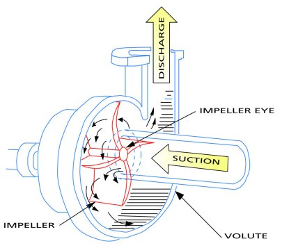
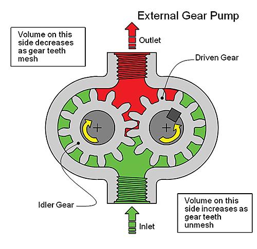
Breaking down the pumps by their mechanics, the gear pump consists of two gears rotating in opposite directions with each gear’s teeth catching fluid and forcing it around the gears and through the outlet. A centrifugal pump has a rotating impeller that creates suction on the inlet and positive pressure on the discharge. The impeller has vanes which the liquid is caught in and increases the outlet pressure of the liquid. When evaluating both pumps the main difference is that in gear pumps the flow rate is proportional to the pump speed and independent of the discharge pressure; while, in the centrifugal pumps the discharge pressure is proportional to the pump speed and independent of the flow rate. These facts directly affect the pros and cons of each pump.
The advantages and disadvantages of each pump type go as follows. For gear pumps the advantages are that pressure change doesn’t impact the efficiency greatly, works with high capacities, not greatly affected by liquids of varying viscosities, and continuous output regardless of discharge pressure. The disadvantages are that a gear pump causes high shear stress on liquids and that the pump will flow output fluid regardless of line blockage. Advantages for centrifugal pumps are that they are easy to clean, will not explode because pump will dead-head and low cost. Disadvantages for them are that flow rate decreases as discharge pressure increases and efficiency is dependent on discharge pressure. Figure 1 and 2 below are very good images of both pumps.

Figure 1, Centrifugal Pump [www.globalspec.com]

Figure 2, Gear Pump Diagram [www.designworldonline.com]
Pump Calculations:
To find the torque of a pump, the load cell force is used to find how much force is being supplied to the pump. The reading from the meter is used along with the load cell factor to find the actual force.
Load Cell Factor:
Force = [N]
Load Cell Reading = [m]
Load Cell Force:
Load cell force = [N]
In order to calculate the amount of power to the pump supplied to the motor, the torque must first be found. This is dependent on the amount of force applied and the length of the lever arm.
Torque:
Lever arm Length [in]
The power supplied to the motor can be found using the torque and how fast the pump is rotating.
Power the pump receives from the motor:
Pm = power supplied to the motor [W]
N= rotational speed [revolutions per ]
T= torque provided to the motor [N*m]
In order to find how efficiently the pump is running, it must first be calculated how much power is being supplied to the fluid from the pump
Power delivered to the fluid by the pump:
P = power delivered by the pump [W]
Pd = pump discharge pressure [Pa]
Q = volumetric flow rate [m3/s]
The efficiency of a pump is an important characteristic as it tells how much of the power put into the pump by the motor is being converted to power supplied by the pump to the fluid. The higher the efficiency, the more power is put into the fluid by the pump.
Efficiency:
= Pump efficiency
In order to find how the velocity of a fluid through the orifice plate, a few different factors must first be known. The first of all being the area of the orifice itself and the second being the pressure drop across the orifice plate.
Orifice Calculations:
Orifice area:
d = orifice diameter [m]
A = area [m2]
Fluid Velocity across orifice:
Uo= fluid velocity [m/s]
Co= 0.61 [unitless, turbulent flow coefficient)
gc= gravity factor [kg*m / s2, 1 for SI units]
ΔP = pressure drop [Pa]
⍴ = density [kg/m3]
Using an ultrasonic flow meter to find the velocity of the fluid, it can be used in conjunction with the cross sectional area of the flow to find the total volumetric flow rate.
Volumetric Flow Rate:
Q = Volumetric flow rate [m3/s]
A = area [m]
Uo = velocity of fluid [m/s]
In order to find the calculated volumetric flow rate, two things must be known. The first is the total volume of the fluid being used and the second being the amount of time it takes for that fluid to be put through the pump in order to calculate the volumetric flow rate. The equation below helps to find the amount of water in the tank.
Volume of the Tank as a function of vertical water level:
V(h) = volume [cm3]
h = height [cm]
a1= area1 [cm2]
a2 = area ratio [unitless]
Safety Precautions
In this experiment, it is required to wear safety glasses and a hard hat at all times. It is necessary to guard against falls, burns, cuts, and other physical hazards. We also need to avoid wearing loose clothes, especially when you are close to the pump belt.When adjusting the gear belt, always turn off the motor control power switch, the power strip switch and the GFCI. Make sure that all of the equipment is well grounded using three-wire plugs. All components should be plugged into the GFCI protected power strip provided with the experiment. Should water be spilled, clean up immediately with paper towels to ensure no slips occur and no electrical equipment is affected.
One main concern with this lab is ensuring there is always flow to the pump. Without flow, the pump will cavitate which can damage the pump. The discharge valve should also always be open as to prevent overpressuring the pump. The inter-tank valve should also be open as much as possible to avoid overfilling the top tank, TK-101.
EnvironmentalBecause we are only using water, there are no environmental concerns. Water is not a skin irritant, is non-hazardous in case of ingestion, and is non-corrosive to the eyes and lungs. No acute or chronic health issue risks are present in this experiment. Also because this system is a closed loop, a large amount of water will be saved in the process as opposed to if this were an open system such as the heat exchanger or piping network lab.


