Numet
ANALOG ELECTRONICS AND DEVICES (EEE 2213)
ASSIGNMENT 1 – AMFLIFIER FREQUENCY RESPONSE
Directions : Students are required to form into group of 2 for this simulation project.
You are required to produce a simulated frequency response, voltage gain versus frequency, of the amplifier circuit given in Figure 1 and 2 by using MULTISIM or of any equivalent software. Print the response. Observe the simulated response and you should be able to determine the following values; the midband gain, Av(mid), the lower critical (i.e. cut-off) frequency, fcl and the upper cut-off frequency, fcu. Record all the values.
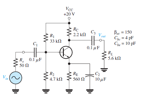 Figure 1
= βdc
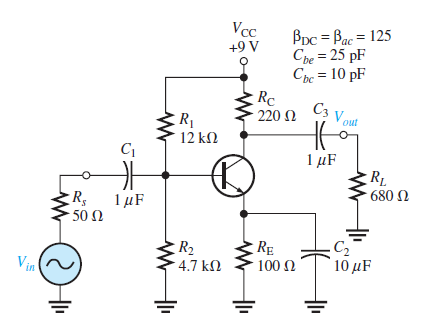 Figure 2
Based on your simulation of the circuit in Figure 1 and 2, answer the followings:
What are the simulated values of fcl, Av(mid) and fcu for the common-emitter amplifier in Figure 1 and Figure 2 ?
Compare these values with the cut-off frequencies obtained from the calculated values.
- Simulated value (CO3; PO3 - 6 marks)
- Calculated (CO3; PO3 - 40 marks)
Which capacitor affects on the lower cut-off frequency and the upper cut-off frequency of the amplifier circuit ?
(CO3; PO3 - 2 marks)
With cut-off frequencies known, calculate the input resistance, Rin, of the amplifier circuit.
(CO3; PO3 - 4 marks)
Discuss your observation on the simulated and the calculated frequency response.
(CO3; PO3 - 2 marks)
NOTES:
1) Submission of simulation report is in group.
2) Submission of calculation and manual sketch of bode plot is individual.
3| PagePrepared by SNMT


