How do I apply the equations in the 3 questions?
EN 5001 Electric Machine

Electric Machine
| Title | Calculation and Simulation on Speed regulation of three-phase induction motor |
| | |
| Design Requirement | There is a wound-type induction motor with Y/y connection. Its parameters are given as follows: Nominal power Design content:
|


 =4 Ω
=4 Ω
 =6 Ω
=6 Ω

 = 2
= 2 . Try to do the calculation by hand of the parameters of machine, draw the mechanical characteristic curves and analyze the power transfer.
1 Principle
1.1 Speed regulation of 3-phase induction motor
The rotating speed of 3-phase induction motor can be expressed as
 (1-1)
(1-1)
According to the equation 1-1,there are two basic ways to regulate the rotating speed of the rotator of induction motor: to change synchronous speed or to change silp.
To change synchronous speed, according to
 there are two way to regulate it, which are frequency regulation and pole regulation.
 to change slip, the main methods include voltage regulation, string resistance on its rotor winding for a wound type rotor induction motor.
1.2 Mechanical Characteristics
The mechanical characteristics of three-phase induction motor are defined as the relationship between rotor rotating speed  and electromagnetic torque
 under the condition of a certain stator voltage, synchronous frequency and other parameters of stator, which can be represented as
 . According to the equivalent circuit of induction motor, the mechanical characteristics can be expressed as:
 (1-2)
(1-2)
The above equation provides the relationship between electromagnetic torque and slip. The mechanical characteristics diagram can also be drawn in Figure 1.1, where the horizontal axis is and the vertical axis represents rotor rotating speed .
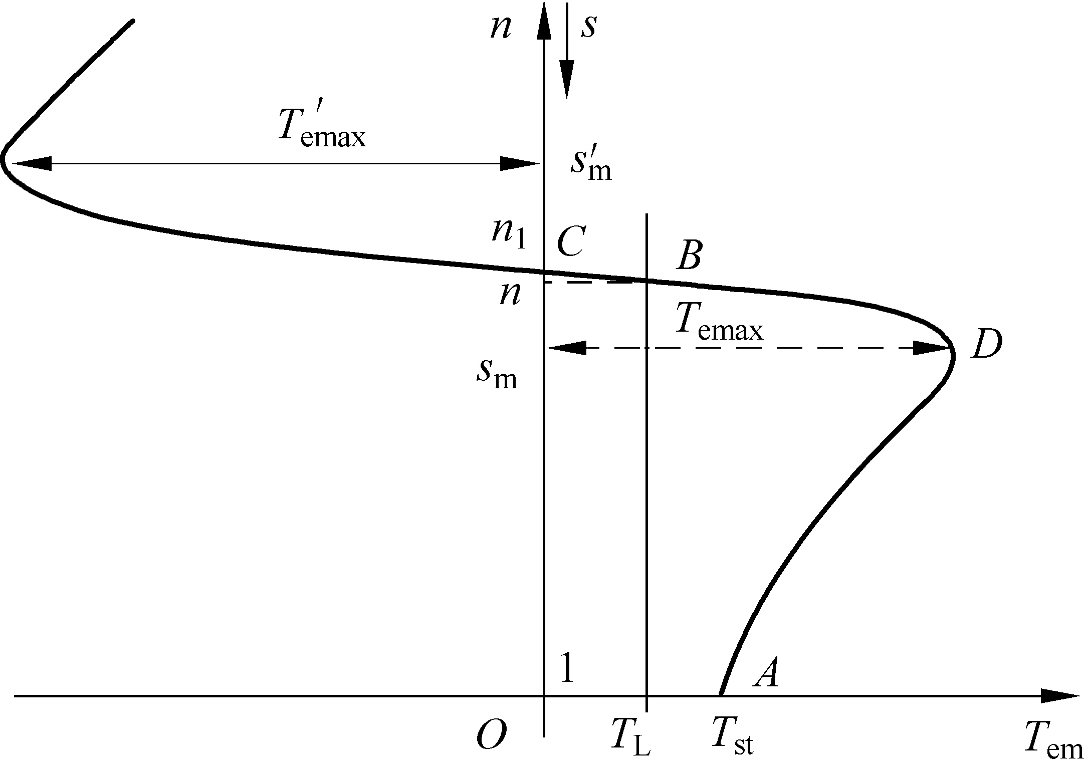
Figure 1.1 Mechanical Characteristic Curve for Induction motor.
1.3 Speed regulation through voltage regulation on stator
According to equation 1-2,when the stator voltage u1 is reduced to different values, since the synchronous speed is fixed, therefore the mechanical curves always have the same synchronous operation point. Considering the maximum electromagnetic torque is proportional to the stator voltage square , the critical slip for the maximum is not dependent on
  . Therefore the mechanical characteristics for different U1 can be sketched as shown in Figure 1.2.
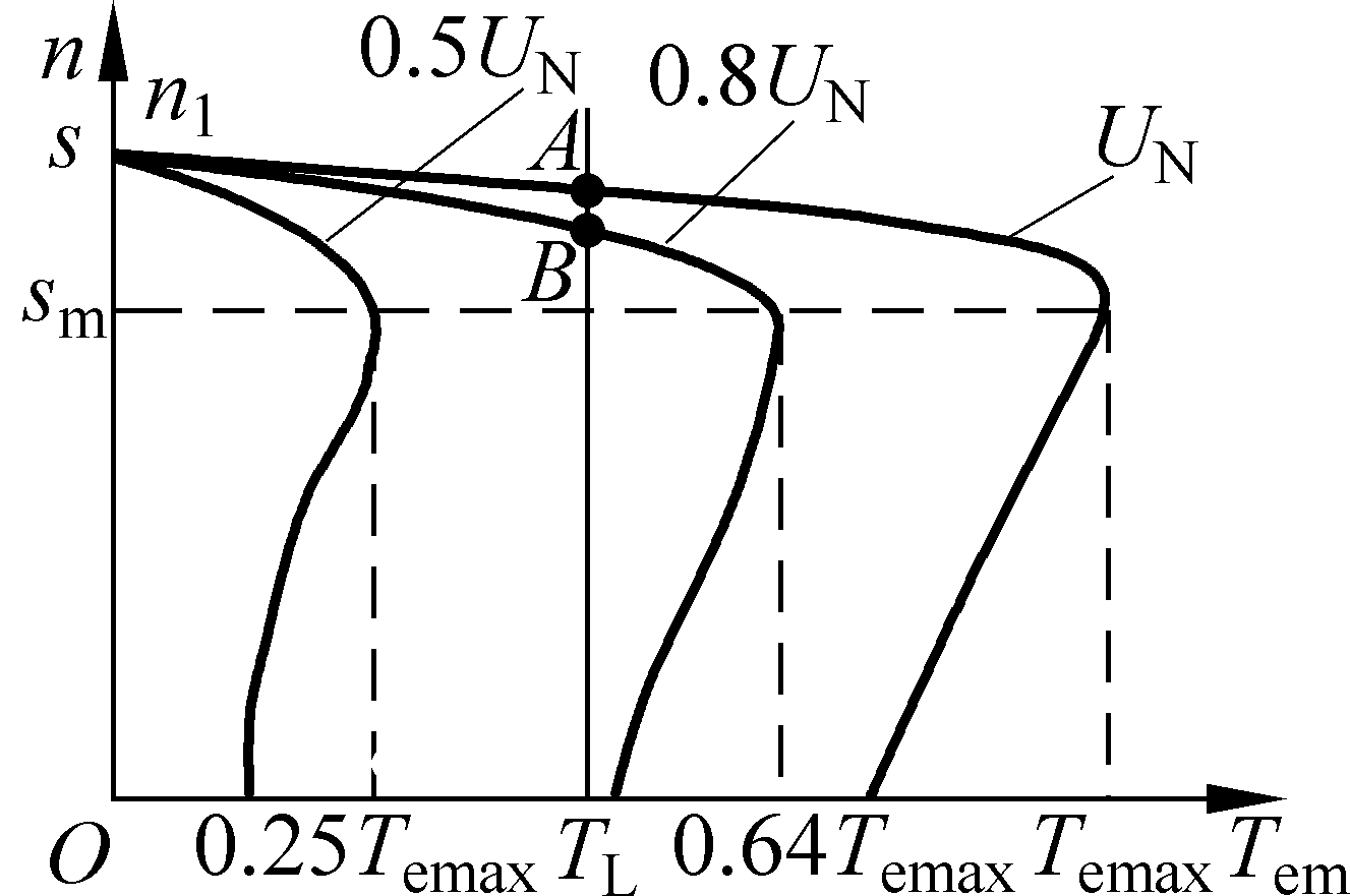
Figure 1.2 The mechanical characteristic curve for varying stator voltages
1.4 Speed regulation through frequency regulation
The induced EMF in the stator can expressed by  . To maintain main magnetic flux
 constant (to not saturate the magnetic circuit) and at the same time achieve speed regulation,it is necessary to maintain formula
  keep constant.
Considering the stator EMF  is difficult to find out. Therefore for the real speed regulation system, it is supposed that
  constant.
Therefore the electromagnetic torque can be expressed as the following equation:
 (1-3)
(1-3)
Therefore the mechanical characteristics curves of induction motor for speed regulation by changing the frequency can be sketched as follows figure 1-3.

Figure 1-3 the mechanical characteristics curves of induction motor for speed regulation by changing the frequency( constant)
1.5 Speed regulation through string resistance of rotor winding
The mechanical characteristics curves of induction motor for speed regulation by connecting a resistor with its rotor winding,

Figure 1-4 The mechanical characteristics curves of induction motor for speed regulation by connecting a resistor with its rotor winding
It is known that  ,maintain the voltage supply output voltage fixed,therefore the main magnetic flux is a constant. During the speed regulation process, in order to make full use of windings, therefore it is necessary to maintain
  ,therefore
 (1-4)
(1-4)
Therefore
 Constant (1-5)
2 Calculations


