Waiting for answer This question has not been answered yet. You can hire a professional tutor to get the answer.
QUESTION
Digital Systems Laboratory
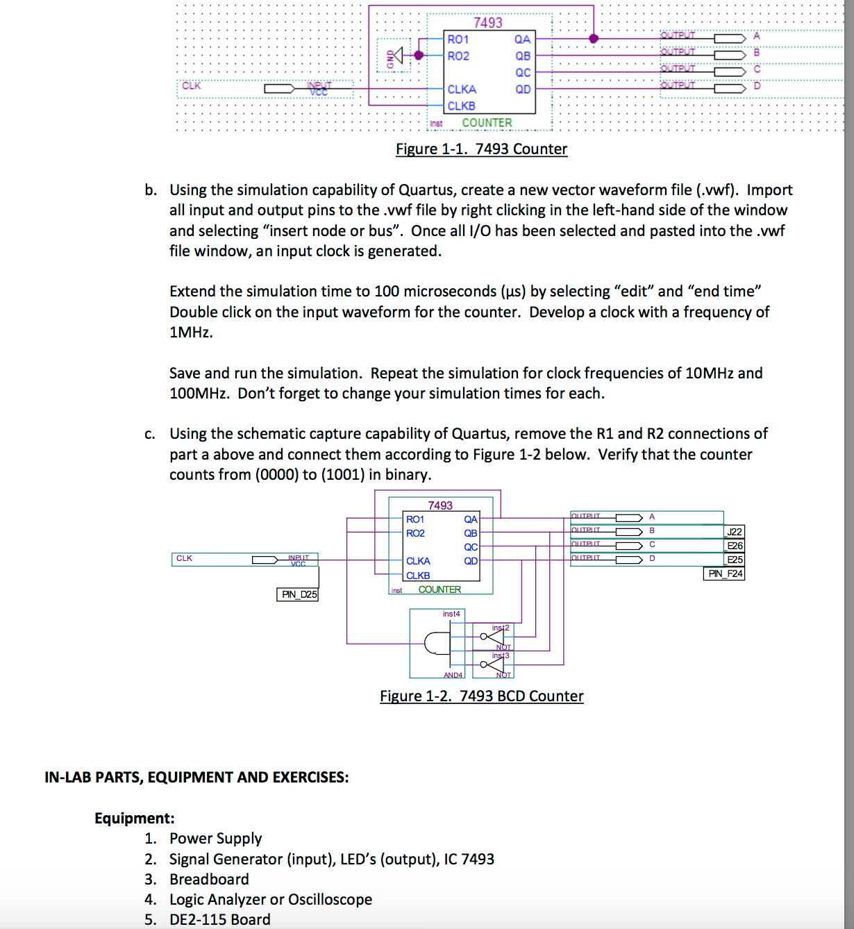
a. Using the schematic capture capability of Quartus, the 7493 counter is set up with an input pin to the CLKA input, and other connections as set up in Figure 1-1. The outputs QA through QD should be routed to output pins. I used the first 4 red LED’s and KEY[0] as the trigger.
