Waiting for answer This question has not been answered yet. You can hire a professional tutor to get the answer.
Strain Gauge Measurement
Safety: Your demonstrator acts as your safety warden. Follow all instructions given by your demonstrator. If the evacuation siren sounds leave your bags and follow the instructions of your demonstrator and proceed to the evacuation area.
Place all weights on holder when not in use.
Electrical: Ensure that all electrical apparatus has no signs of obvious damage. Report any damaged apparatus to your demonstrator.
Do not attempt to fix any broken apparatus. Report any damage to your demonstrator.
General: No food or drink is allowed in the laboratory.
Introduction: Strain Gauges are used in many systems to measure the deformation of structures and materials, from this forces, moments and stress can be calculated. In this experiment we will be looking at a system of seven strain gauges spread over the length of a steel cantilever beam and will be comparing the measured strain and stress with the
theoretical strain and stress.
Theoretical Strain:
e =Mc/IE
Where:
e is strain
M is the moment
c is the distance from centre of beam to point where strain is bean calculated
E is the youngs modulus
I is the second moment of inertia
Theoretical Stress:
O=M/S
Where:
S is the section modulus
Measured Stress:
O=Ee
Where:
is the measured strain
Apparatus: Slotted masses Strain Gauge Gauge Reader Steel Beam Clamp
Connecting Wires
Rule
Digital Callipers
Side Cutters
Procedure:
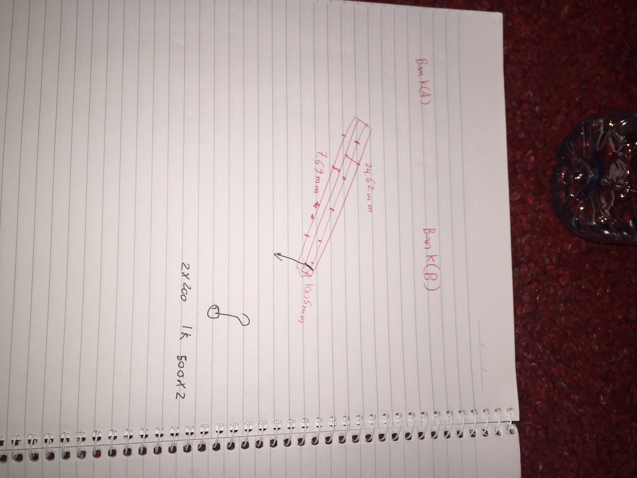
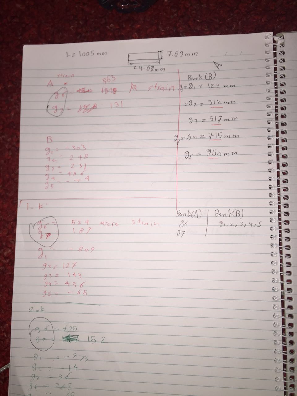
1. Measure all required beam dimension using digital callipers and tape measure.
2. Connect all strain gauge wires to the gauge reader (information below). Check that all gauges are working by weighting the beam and checking for a change in strain.
3. Document initial readings for all strain gauges.
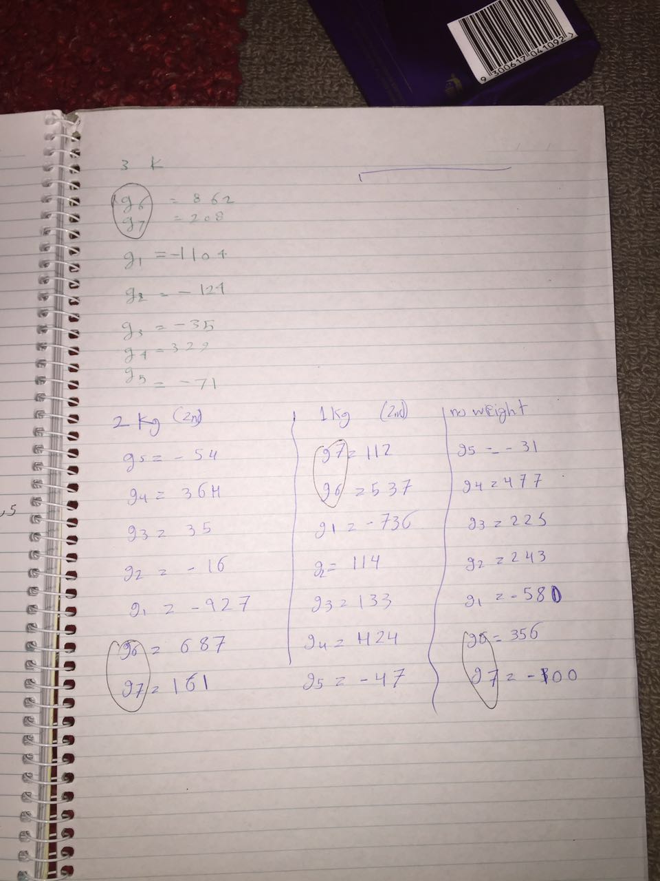
4. Apply 1kg of mass to the beam and document the new strain readings. Repeat for 2 and 3kgs.
5. Remove 1kg of mass and document the new readings. Repeat until all masses are removed.
Gauge Reader
As seen in Figure 1 the gauge reader consists of two banks and twelve position allowing up to 24 strain gauges to be positioned simultaneously. The reader has already been calibrated for 120ohm strain gauges with a gauge factor (k) of 2.09.
Connecting a strain gauge
1. Disconnect the power
2. Choose a free position in a bank and connect the white and black wires to the black pin and red wire to the red pin.
3. Connect Power.
4. Move position and bank dials to the strain gauge position
5. Deform the material to ensure the strain gauge is working
Figure 1 Gauge Reader
Report:
Provide an individual report. Although no minimum word count provided, I expect a high quality 3rd year engineers report. It must include (but not limited to).
Summary: Contents: Introduction: Procedure:
*Results:
*Conclusion/Discussion: Appendices:
*emphasis should be put on these areas.
--------------------------------------------------
3 kg
1=-1104
2=-124
3=-35
4=329
5=-71
6=862
7=208
------
2kg
1=-973
2=-14
3=36
4=368
5=68
6=695
7=152
