Waiting for answer This question has not been answered yet. You can hire a professional tutor to get the answer.
QUESTION
Week 5 Lab
*** This lab has to be implemented only in hardware (using NI myDAQ) ***
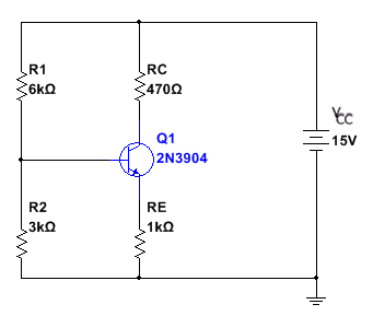
- Analyze the circuit in the Figure 1 below to calculate the following values: VBB, VE, IE, VC and VCE. Make sure to include 20% tolerance for each resistor in the calculations.
- Construct the circuit shown in Figure 1 below on the breadboard using the transistor and two resistors (RCand RE).
Figure 1
- Using the jumper wires, screw driver and screw terminal connector, connect the board to NI MyDAQ Instrument Device.
- Use channel +15V pin out on the NI myDAQ Instrument Device to provide the supply voltage (VCC). Use channel AI0 to measure the required voltages: VBB, VE and VC and currents: IC and IE using the Multimeter.
- Tabulate the data from step 1 and step 5.
CalculatedMeasured
VBB
VE
VC
IE
IC
- Short the resistor R2 and calculate the values in steps 1.
- Modify the circuit in Figure 1 to short the resistor R2 and measure the values in step 4.
Measured values with R2 shorted
VBB
VE
VC
IE
IC
Review questions:
- Compare a calculated and measured values in the table. Discuss whether the values are the same of different. If they are different, provide the reasoning. And how to reduce this difference between calculated and measured values.
- What happens when R2 is shorted? Why does the measured values change?
- If the NPN transistor is replaced with a PNP transistor, how does the change in the transistor effect the current and voltage in the circuit?
Deliverables:
- Analysis of the circuit and calculations of voltages: VBB, VE and VC and currents: IC and IE.
- Place your student ID card on the breadboard and take a picture of the circuit board and pin out on the NI myDAQ Instrument Device.
- Take screenshots of the measurements obtained from function generator and Multimeter on the NI ELVISmx Instrument Launcher on your screen.
Lab Report:
- Use the Lab report template found in the “Tools and Template” link in the navigation center.
- Include all the deliverables.
- Include all the screenshots of the measurements from circuit design on the breadboard using NI myDAQ Instrument Device and measurements from MI ELVISmx Instrument Launcher.
- Save the document as Lab5YourGID.docx (ex: Lab5G00000000.docx) and submit in Blackboard.
Files:
W5_lab.png
